

Quantitative material throwing device for aquaculture
An aquaculture, quantitative warehouse technology, applied in the application, fish farming, animal husbandry and other directions, can solve the problem of uneven feeding of the feed, and achieve the effects of simple structure, prevention of overburden, and low manufacturing cost.
- Summary
- Abstract
- Description
- Claims
- Application Information
AI Technical Summary
Problems solved by technology
Method used
Image

Examples
Embodiment 1
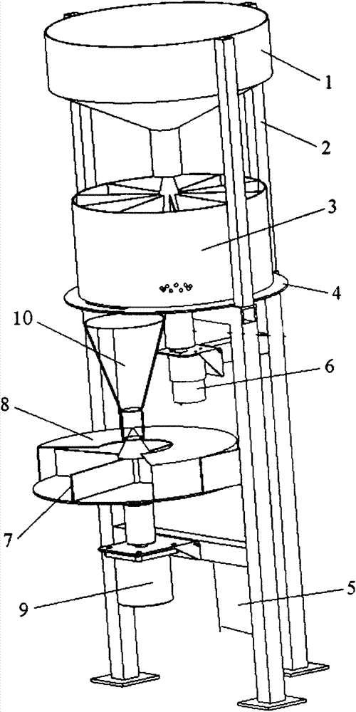
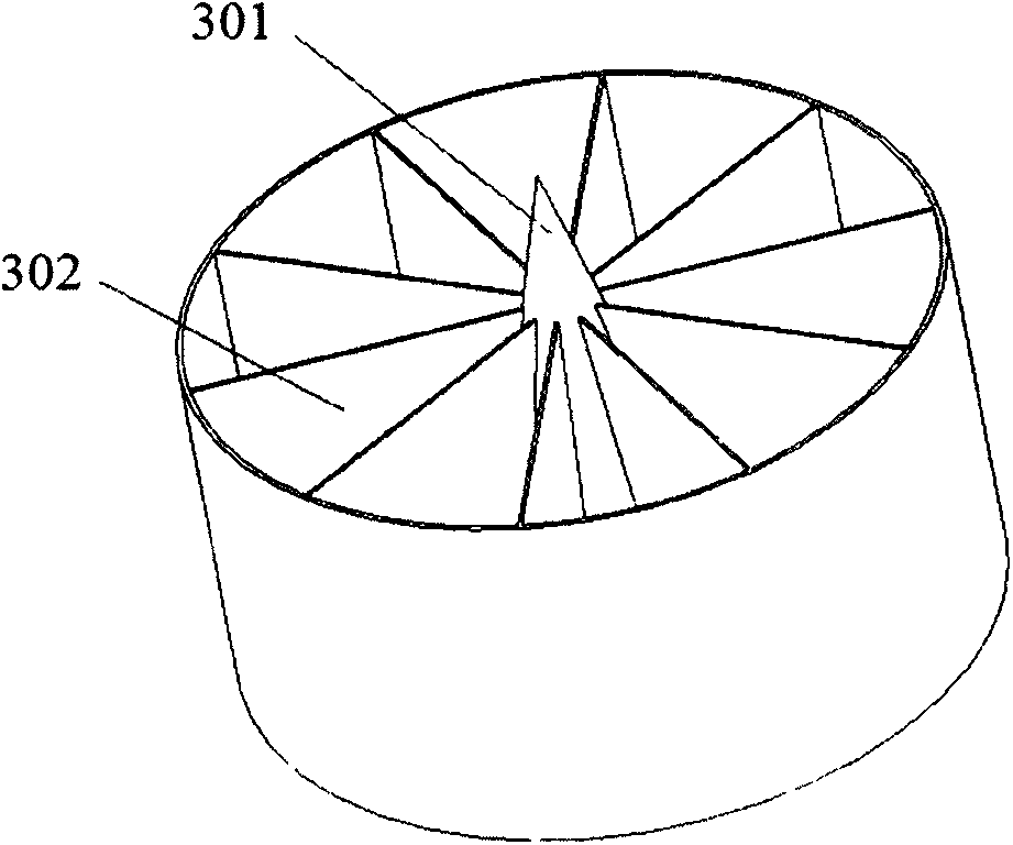
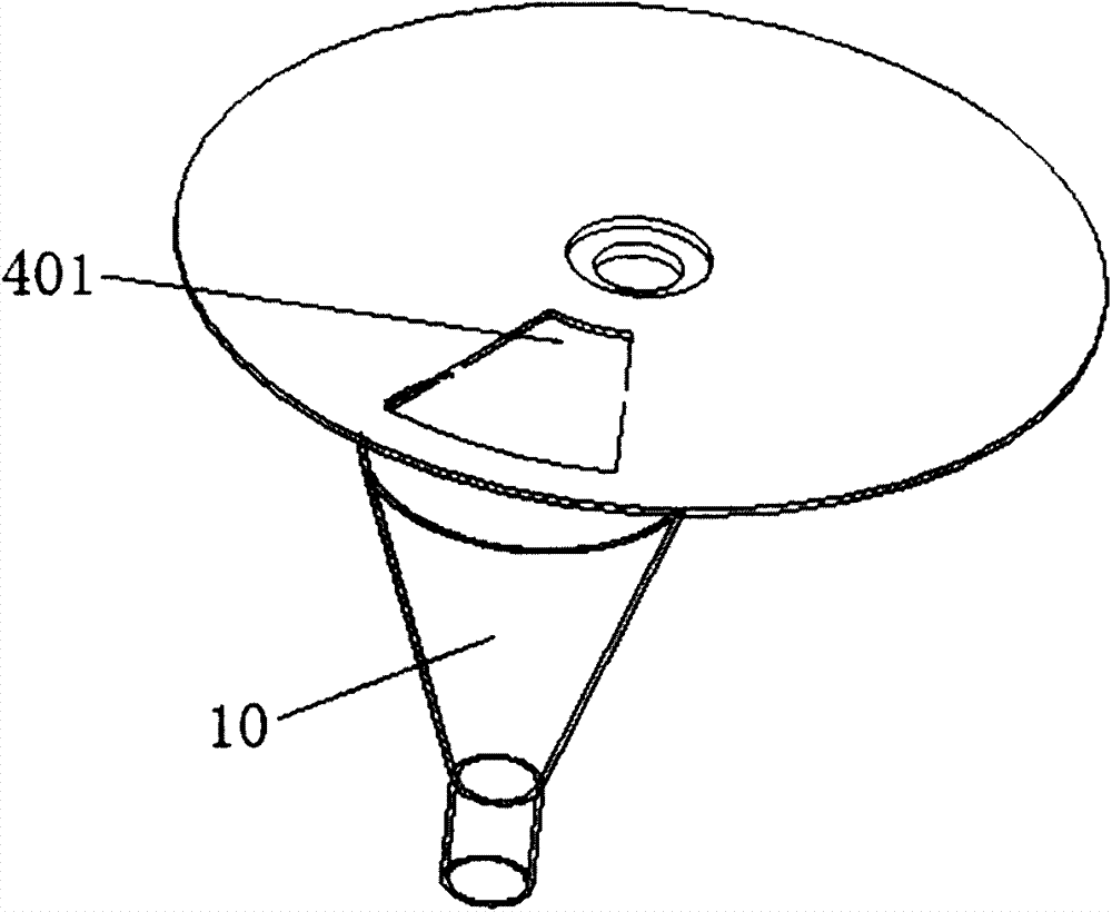
[0034] combine figure 1 , a quantitative throwing device for aquaculture of the present embodiment, comprising a storage bin 1, a support 2, a quantitative bin 3, a quantitative tray 4, a feeding pipe 10, a feeding motor 6, a throwing tray 7, and a throwing protection Cover 8, material throwing motor 9 and controller 5. The storage bin 1 is funnel-shaped, and its upper opening is much larger than the lower opening. The storage bin 1 is fixedly installed on the top of the bracket 2, and can be fixed by welding or fasteners. The quantitative bin 3 is installed below the storage bin 1, and is connected with the feeding motor 6, and the quantitative bin 3 is driven to rotate by the feeding motor 6. Such as figure 2 As shown, the quantitative bin 3 includes a quantitative cone 301 and a quantitative compartment 302. The quantitative compartment 302 is divided into equal parts by the partitions that radiate outward from the quantitative cone 301. The tip of the quantitative cone ...
Embodiment 2
[0037] The basic structure of a quantitative throwing device for aquaculture in this embodiment is the same as in Embodiment 1, the difference is that there is a gap of 2 mm between the quantitative bin 3 and the quantitative disc 4 in this embodiment for throwing The use of granular feed ensures that there will be no friction between the quantitative bin 3 and the quantitative disc 4, reducing the noise of the device running.
[0038] In order to better understand the content of the present invention, the working process of a quantitative throwing device for aquaculture of the present invention is given now.
[0039] see figure 1 , a quantitative throwing device for aquaculture of the present invention, during work, feed is stored in the storage bin 1, and the feeding motor 6 and the throwing motor 9 rotate at a certain speed under the action of the controller 5, Thereby drive quantitative bin 3 and throwing material dish 7 to rotate. The feed flows out from the outlet of t...
PUM
 Abstract
Description
Claims
Application Information