
Spinal implant structure body and suites thereof

A technique of structure, spine

Inactive Publication Date: 2014-06-25
曾昌和
View PDF6 Cites 3 Cited by
  • Summary
  • Abstract
  • Description
  • Claims
  • Application Information

AI Technical Summary

Problems solved by technology

However, these conventional designs are not ideal and there is still room for improvement

Method used


Image

  • Spinal implant structure body and suites thereof
  • Spinal implant structure body and suites thereof
  • Spinal implant structure body and suites thereof

Examples


Embodiment Construction

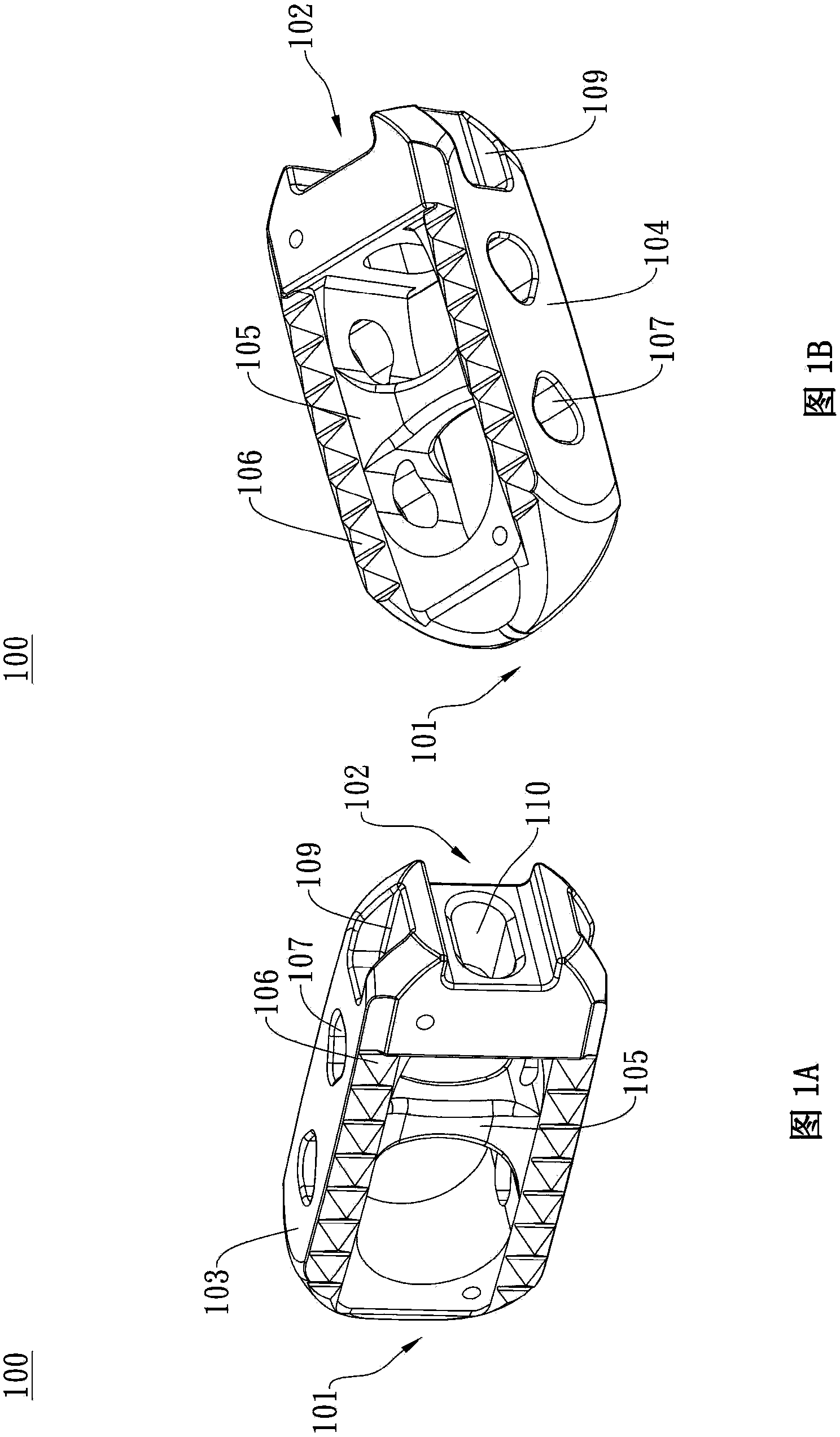
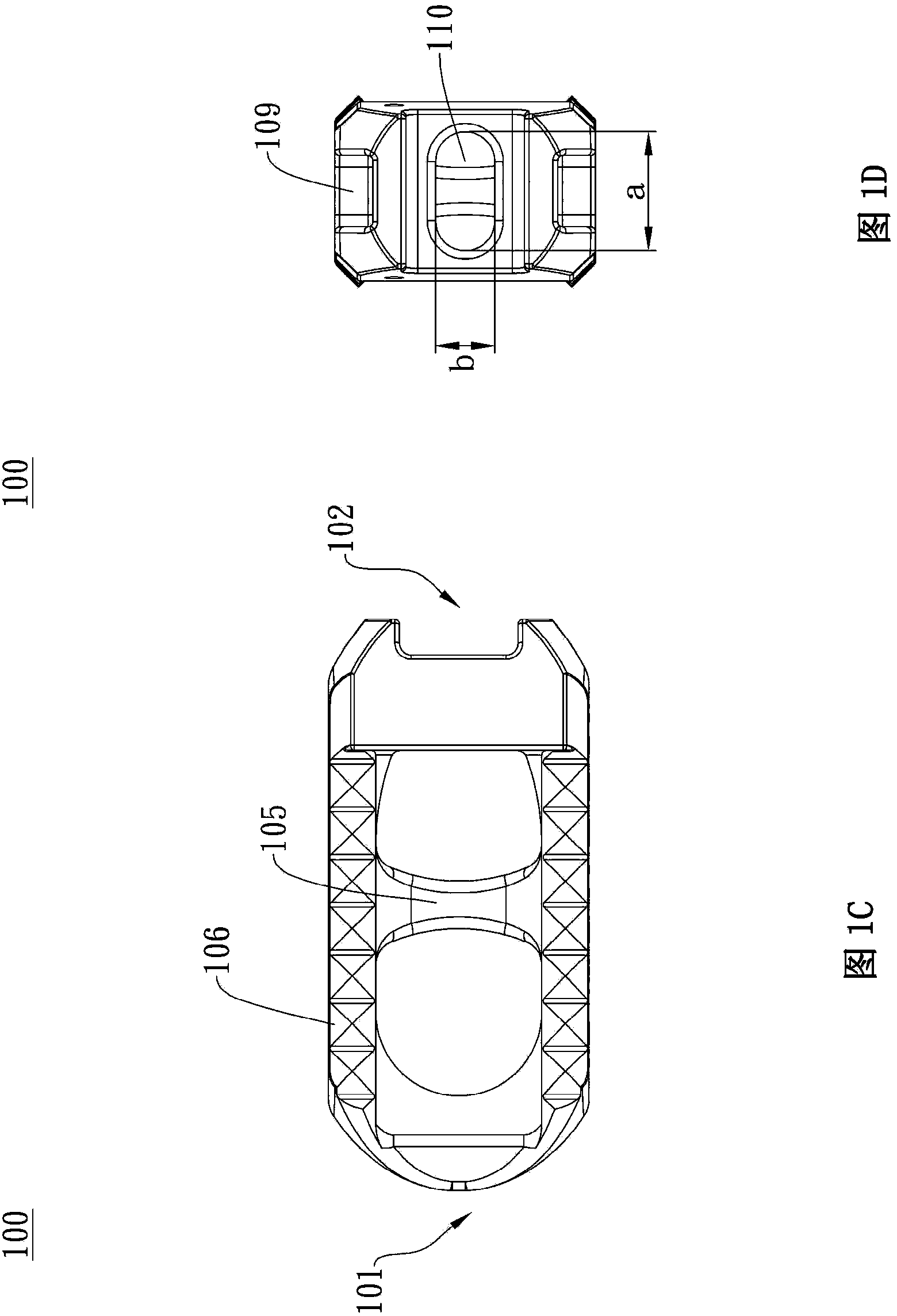
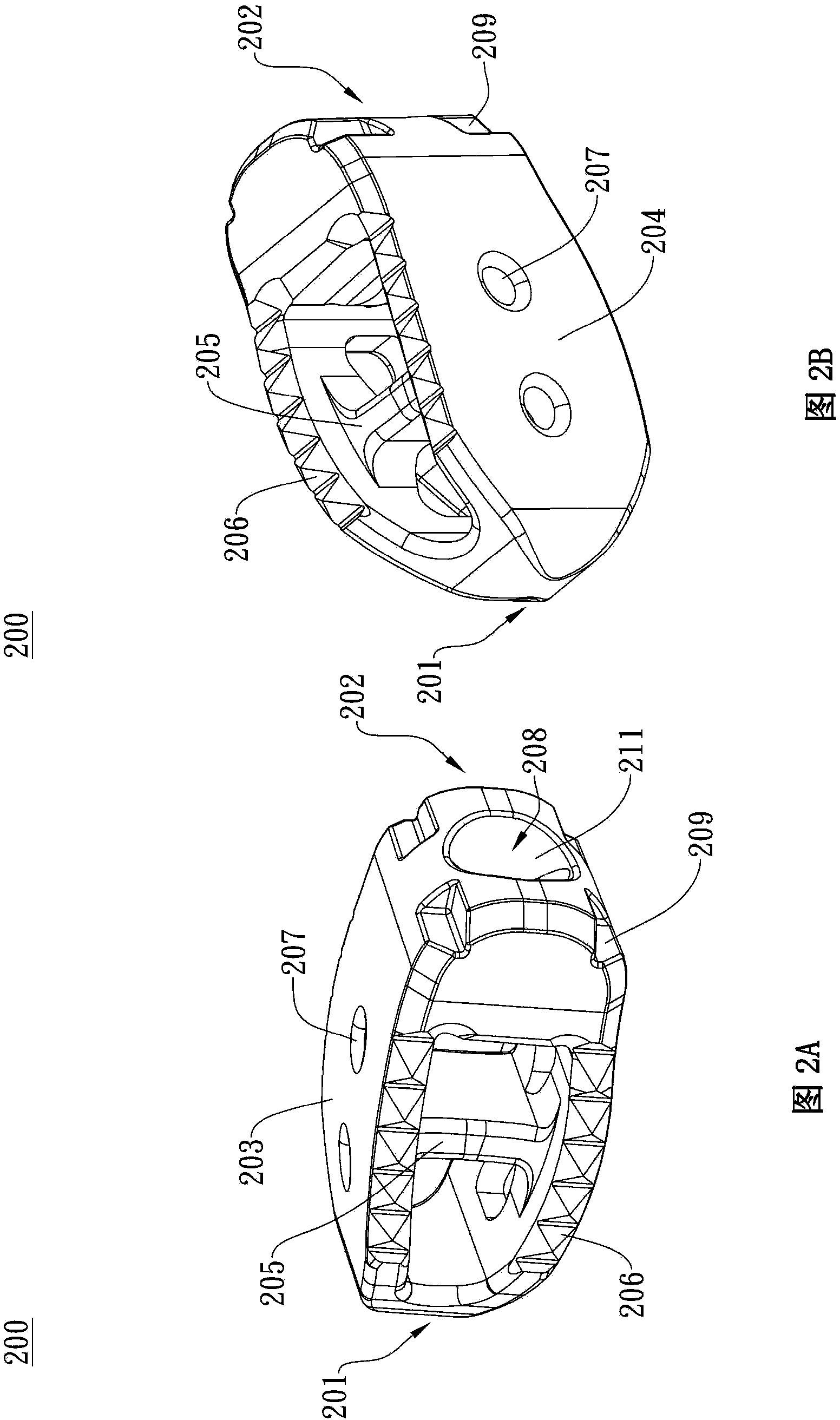
[0168] In order to have a clearer understanding of the technical features, purposes and effects of the present invention, the specific implementation manners of the present invention will now be described with reference to the accompanying drawings.

[0169] The following specific examples are only illustrations of the preferred embodiments of the present invention, and are not intended to limit the scope of the present invention. Those skilled in the art can make appropriate changes and corrections through the disclosure of the present invention without departing from the spirit of the present invention. It should be noted that the following drawings are only used as an example to present the shapes and relative positions of the components of the present invention, and are not intended to limit the proportional relationship of the various components.

[0170] The spinal implant kit of the present invention includes a spinal implant structure and an operating tool, and its mat...


PUM


Abstract

The invention discloses a spinal implant structure body and suites thereof, wherein the spinal implant suites comprises a spinal implant structure body and an operation tool. The spinal implant structure body comprises a hollow body; the hollow body has a front wall, a back wall, and a separating wall set inside the hollow body; one end of the hollow body is provided with a recess and a long through hole, and the recess has a curved surface; at least one inserting groove is set in the hollow body; the at least one inserting groove is set on the surface of the one end of the recess in the hollow body, and is set around the recess. The operation tool is designed particularly to match the structure of the spinal implant structure body. The structure of the spinal implant suites is configured to help vertebral foramen approach arthrodesis, and improve operation efficiency.

Description

technical field [0001] The invention relates to a spinal implant structure and its kit, in particular to a spinal implant structure and its kit suitable for transforaminal interbody fusion (Transforaminal Lumbar Interbody Fusion). Background technique [0002] The spinal implant structure is an artificial implant used to replace the diseased intervertebral disc in bone fusion surgery to provide support and enhance the stability of the spine; the middle of the spinal implant structure can be filled with autologous bone or artificial bone tissue, to promote bone fusion. [0003] Transforaminal Lumbar Interbody Fusion (TLIF) is an emerging surgical method for the treatment of lumbar degenerative diseases. Compared with posterolateral lumbar fusion (PLF) and posterior interbody fusion (PLIF), TLIF has the advantages of good prognosis and fewer complications, so patients can recover from surgery faster. In recent years, combined with minimally invasive surgical techniques, TLIF...

Claims


Application Information

Patent Timeline
Patent Type & Authority Applications(China)
IPC IPC(8): A61F2/44
CPCA61F2/44A61F2002/30001
Inventor 曾昌和
Owner 曾昌和
Learn More