Continuous casting machine tundish submerged nozzle baking furnace

An immersion and tundish technology, which is applied in foundry equipment, casting melt containers, metal processing equipment, etc., can solve the problems of the adverse effect of the surface baking temperature of the immersion nozzle, the inability to adjust the gas concentration, and the influence of the baking effect, etc. To achieve the effect of convenient movement and crane hoisting, full use of energy, and convenient crane hoisting

Inactive Publication Date: 2016-06-08
JIGANG GRP
View PDF13 Cites 3 Cited by
  • Summary
  • Abstract
  • Description
  • Claims
  • Application Information

AI Technical Summary

Problems solved by technology

[0003] At present, most of the existing immersion nozzle ovens are equipped with exhaust ducts in the oven to discharge the burned gas. The advantage is that it can ensure that the nozzles are baked under airtight conditions and achieve the purpose of making full use of energy. , but approaching the equipment under the condition of insufficient gas combustion is likely to cause CO poisoning and personal injury; in addition, most of the existing immersion nozzle baking furnaces only have one baking chamber in the furnace body. When the production volume is large or In the event of an emergency, once a fault occurs and needs maintenance, it will have a great impact on production; in addition, most of the existing immersion nozzle baking furnaces cannot control the concentration of gas in the combustion mixture during the baking process. Adjustment will adversely affect the baking temperature on the surface of the submerged nozzle, thereby affecting the final baking effect, which is the deficiency in the prior art

Method used


Image

  • Continuous casting machine tundish submerged nozzle baking furnace
  • Continuous casting machine tundish submerged nozzle baking furnace

Examples


Embodiment Construction

[0018] The technical scheme of the present invention will be described in detail below in conjunction with the accompanying drawings.

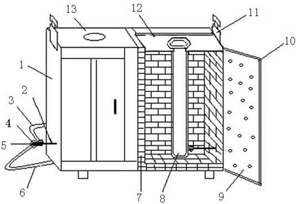
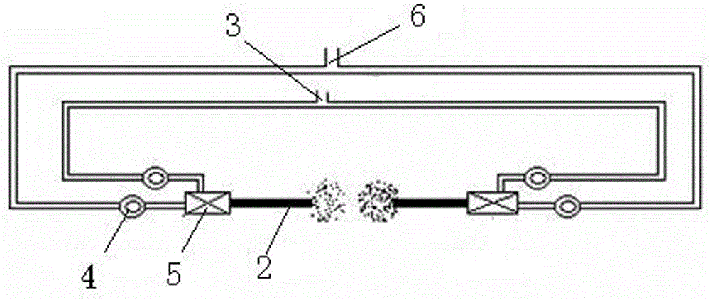
[0019] Such as figure 1 with figure 2 As shown, the continuous casting machine tundish submerged nozzle baking furnace of the present invention includes a furnace body 1, and two baking chambers are arranged in the furnace body 1, and each baking chamber is provided with a nozzle 2, and the nozzle 2 A mixing valve 5 is connected, the mixing valve 5 is connected with the air inlet pipe 6 and the gas inlet pipe 3, the air inlet pipe 6 and the gas inlet pipe 3 are provided with a control hand valve 4, the top of the baking chamber is provided with a mounting plate 12, and the installation The plate 12 is provided with a card slot for fixing the submerged nozzle 8, the furnace body 1 is provided with a furnace door 10, the inner side of the furnace door 10 is provided with an insulating layer 9, the inner wall of the baking chamber is provided w...


PUM


Abstract

The invention relates to the field of metallurgical equipment, in particular to a continuous casting machine tundish submersed nozzle baking furnace. The continuous casting machine tundish submersed nozzle baking furnace comprises a furnace body, wherein two baking chambers are arranged in the furnace body, each baking chamber is provided with a spraying nozzle, each spraying nozzle is connected with a mixing valve, each mixing valve is connected with an air inlet pipe and a fuel gas inlet pipe, each air inlet pipe and each fuel gas inlet pipe are respectively provided with a control hand valve, an installation plate is arranged at the top of each baking chamber, a clamping groove is formed in each installation plate to fix a submersed nozzle, the furnace body is provided with a furnace door, a heat-preservation layer is arranged at the inner side of the furnace door, a flame retardant layer is arranged on the inner wall of each baking chamber, a heat preservation plate is formed at the top of the furnace body and provided with openings matched with the submersed nozzles, pulleys are arranged at the bottom of the furnace body, and pothooks are arranged at the top of the furnace body. The continuous casting machine tundish submersed nozzle baking furnace has the advantages of being safe to operate, capable of meeting production requirements, capable of guaranteeing baking quality and convenient to move and transport, saving energy and the like.

Description

technical field [0001] The invention relates to the field of metallurgical equipment, in particular to a continuous casting machine tundish submerged nozzle baking furnace. Background technique [0002] The submerged nozzle is located between the continuous casting tundish and the mold, and is a guide pipe for molten steel to flow from the tundish to the mold. Its function is to prevent secondary oxidation of molten steel, control the flow state and injection speed of molten steel, promote the floating of inclusions, prevent mold slag and non-metallic inclusions from being involved in molten steel, etc. With the development of science and technology, the requirements for steel properties are becoming increasingly stringent. The submerged nozzle has become one of the most important functional refractory materials to prevent secondary oxidation of the injection flow from the tundish to the crystallizer and improve the cleanliness of steel. In the process of using the submerge...

Claims


Application Information

Patent Timeline
Patent Type & Authority Patents(China)
IPC IPC(8): B22D41/60
Inventor 王刚张树彬孙建华刘永平赵登报柳彩枫张明国潘清红刘德宏时成金赵效伦马玉沅魏鹏举刘鹏陈刚
Owner JIGANG GRP
Why Eureka
Try Eureka