
Digital controlled drill

A technology of CNC drilling machine and ball screw, which is applied to the parts of boring machine/drilling machine, boring/drilling, drilling/drilling equipment, etc. Loss of bed and other issues

Inactive Publication Date: 2014-06-25
江苏映彤机械设备有限公司
View PDF9 Cites 5 Cited by
  • Summary
  • Abstract
  • Description
  • Claims
  • Application Information

AI Technical Summary

Problems solved by technology

[0002] At present, the main function of the CNC drilling machine in the existing technology is mainly drilling, and the milling and tapping functions are difficult to realize, and the rigid sliding guide rail is used. Oil, if the lubrication is insufficient, it will cause direct friction between the metal on the contact surface and wear the bed
Moreover, the original CNC drilling machine's Z-direction spindle box cannot move freely up and down in the Z-axis direction, and only relies on the movement of the Morse spindle to move up and down. The Z-axis stroke is only 240mm, and the Z-axis stroke is limited.

Method used


Image

  • Digital controlled drill

Examples


Embodiment Construction

[0010] In order to make the content of the present invention more clearly understood, the present invention will be further described in detail below based on specific embodiments and in conjunction with the accompanying drawings.

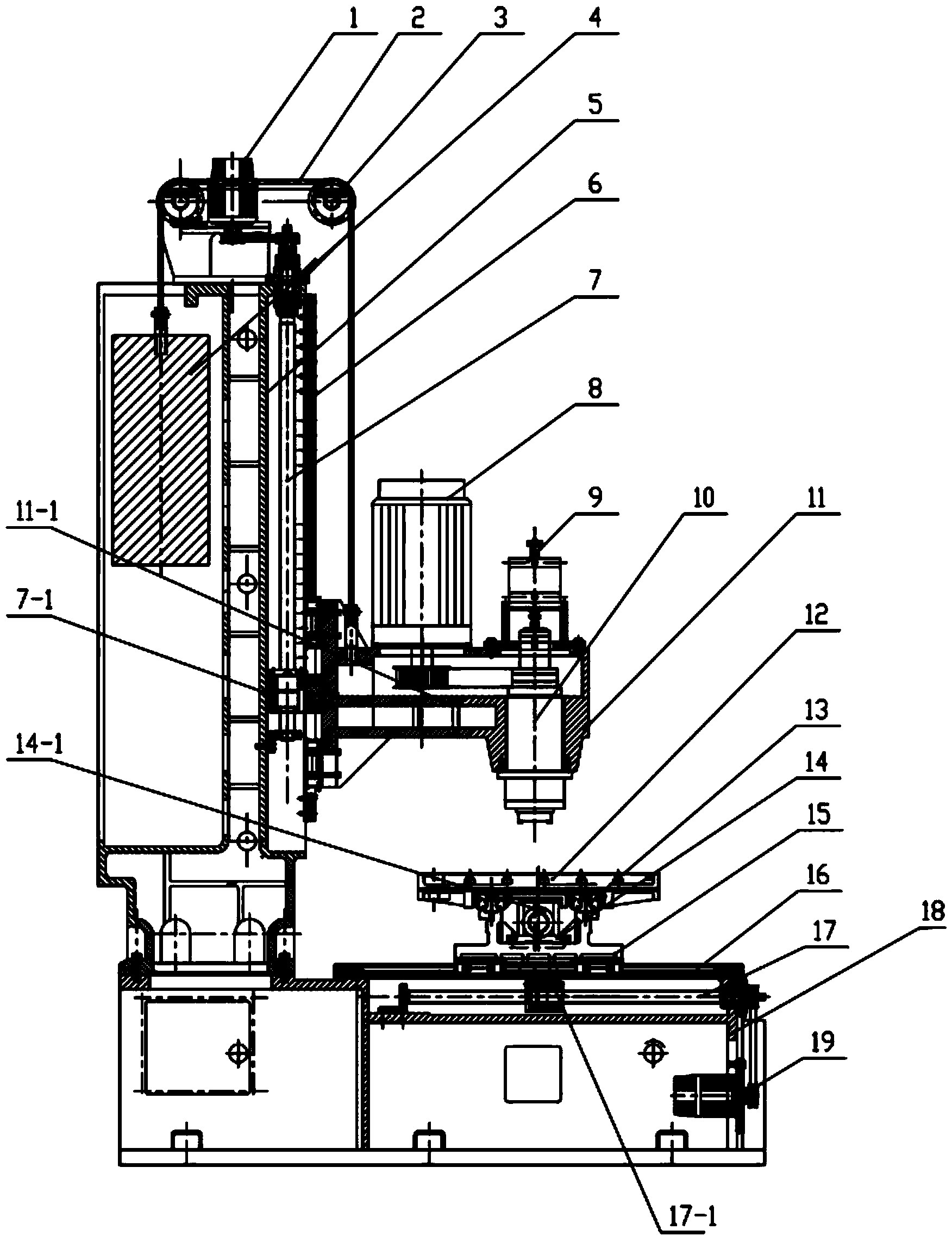
[0011] Such as figure 1 As shown, a CNC drilling machine includes a base 18, a Y-direction servo motor 19, a Y-direction rolling linear guide pair 16, a Y-direction ball screw 17, a Y-direction drive nut 17-1, a Y-direction slide table 15, and an X-direction Servo motor, X-direction rolling linear guide pair 13, X-direction ball screw 14, X-direction drive nut 14-1, worktable 12, Z-direction servo motor 1, Z-direction ball screw 7, drive nut 7-1, Z-direction spindle box 11, Z-direction rolling linear guide pair 6 and column 5, column 5 is installed on the base, Z-direction servo motor 1 is movably connected with Z-direction ball screw 7 through transmission mechanism so as to drive Z-direction ball screw 7 Rotate, the Z-direction ball screw 7 is r...


PUM


Abstract

The invention discloses a digital controlled drill which comprises a base, a Y-oriented servo motor, a Y-oriented rolling linear guide rail pair, a Y-oriented ball screw, a Y-oriented drive nut, a Y-oriented sliding table, an X-oriented servo motor, an X-oriented rolling linear guide rail pair, an X-oriented ball screw, an X-oriented drive nut, a working table, a Z-oriented servo motor, a Z-oriented ball screw, a drive nut, a Z-oriented main shaft box, a Z-oriented rolling linear guide rail pair and a stand column. The stand column is installed on the base, the Z-oriented servo motor is movably connected with the Z-oriented ball screw through a transmission mechanism so as to drive the Z-oriented ball screw to rotate, the Z-oriented ball screw is rotatably supported on the stand column, the drive nut is movably connected to the Z-oriented ball screw through threads, the Z-oriented main shaft box is fixedly connected with the drive nut, the Z-oriented rolling linear guide rail pair is arranged between the stand column and the Z-oriented main shaft box, and the working table is located below the Z-oriented main shaft box. According to the drill, moving strokes can be increased in the X direction, the Y direction and the Z direction, the machining range of workpieces is widened, meanwhile, the electric power loss amount can be reduced, cost is saved, and precise positioning and machining of the workpieces can be achieved.

Description

technical field [0001] The invention relates to a numerically controlled drilling machine, which belongs to the technical field of drilling machines. Background technique [0002] At present, the main function of the CNC drilling machine in the existing technology is mainly drilling, and the milling and tapping functions are difficult to realize, and the rigid sliding guide rail is used. Oil, if the lubrication is insufficient, it will cause direct friction of the metal on the contact surface and wear the bed. Moreover, the Z-direction spindle box of the original CNC drilling machine cannot move freely up and down in the Z-axis direction, and only relies on the movement of the Morse spindle to move up and down. The Z-axis stroke is only 240mm, and the Z-axis stroke is limited. Contents of the invention [0003] The technical problem to be solved by the present invention is to overcome the defects of the prior art and provide a numerical control drilling machine, which can...

Claims


Application Information

Patent Timeline
IPC IPC(8): B23B39/10B23B47/20
CPCB23B39/10B23Q5/28
Inventor 朱丙华
Owner 江苏映彤机械设备有限公司
Learn More