Main cylinder dyeing liquor evenly-distributing device of high-temperature and high-pressure cone dyeing machine

A package dyeing machine, high temperature and high pressure technology, which is applied in the processing of textile material equipment configuration, liquid/gas/vapor yarn/filament processing, textile material carrier processing, etc. Large and other problems to achieve the effect of ensuring uniformity and dyeing quality

Active Publication Date: 2014-06-25
WUXI DONGBAO MACHINERY MFG
View PDF3 Cites 4 Cited by
  • Summary
  • Abstract
  • Description
  • Claims
  • Application Information

AI Technical Summary

Problems solved by technology

Because the existing high-temperature and high-pressure package dyeing machine uses the main pump to start dyeing the package yarn in the entire sarong, which makes the dye liquor flowing back into the main vat still evenly distributed, but due to this working method, the main pump After opening, the pressure of the bobbins in the entire sarong needs to be supplied at the same time, which makes the main pump work more powerful and consumes more energy, and because it needs to ensure sufficient pressure, it uses a lot of water. Therefore, our company has designed a uniform dyeing solution. Distributed dyeing structure, all bobbins of bobbins in the sarong are evenly divided into several blocks. After the main pump is turned on, the dye liquor flows into the dye liquor chamber below the corresponding block, and then flows into the bobbins of the bobbins at the corresponding block positions. Dyeing, which makes the used dye solution flow into the main vat from a concentrated area of ​​the sarong. At this time, the uniformity of the dye solution flowing into the main vat is inconsistent, which will lead to uneven dyeing and affect the entire dyeing.

Method used


Image

  • Main cylinder dyeing liquor evenly-distributing device of high-temperature and high-pressure cone dyeing machine
  • Main cylinder dyeing liquor evenly-distributing device of high-temperature and high-pressure cone dyeing machine

Examples


Embodiment Construction

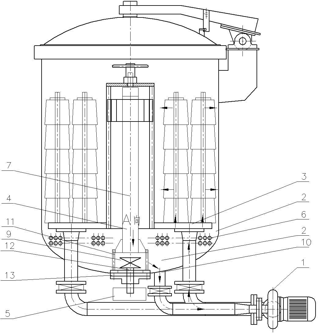
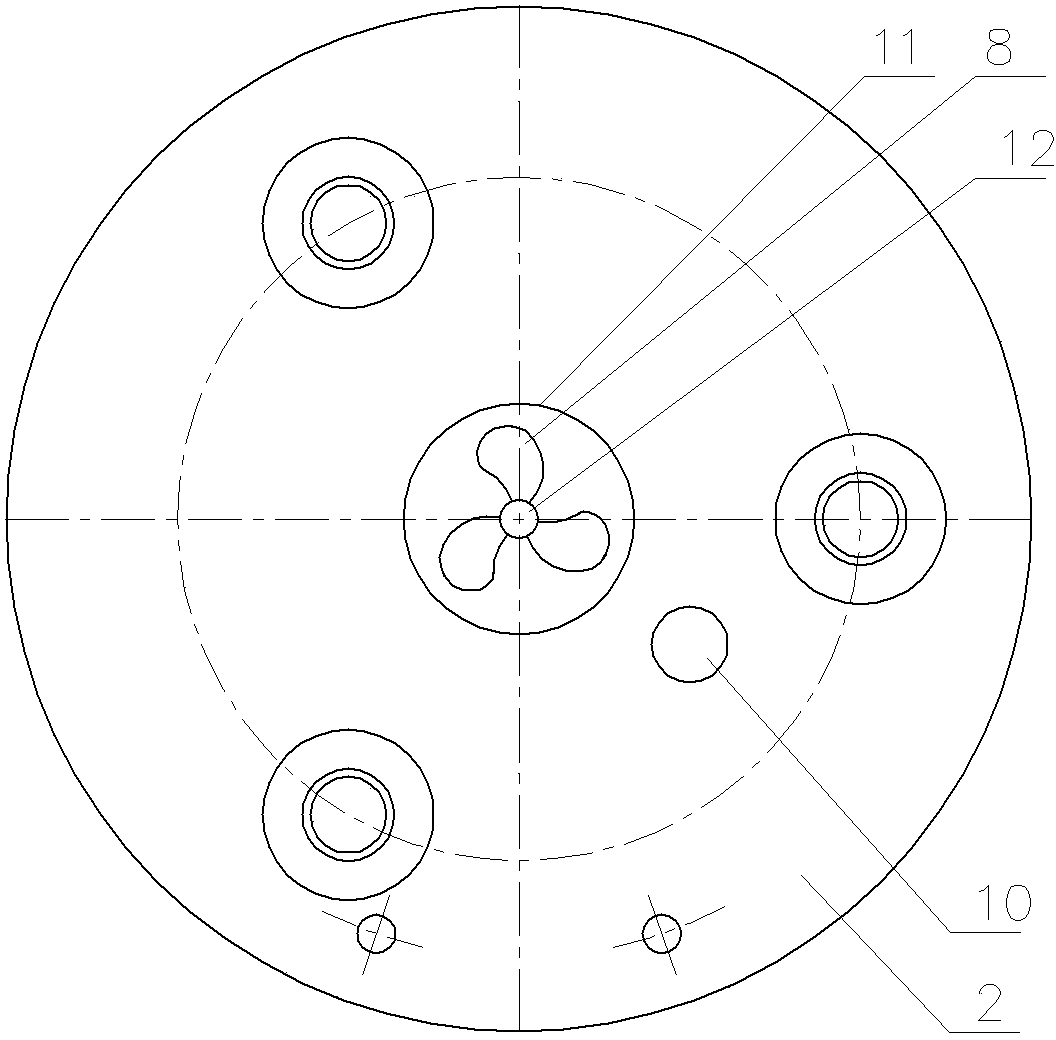
[0011] A device for evenly distributing the dye solution in the main cylinder of a high-temperature and high-pressure package dyeing machine, see figure 1 , figure 2 : It comprises sarong bottom main cylinder 2, sarong 3, sarong central tube 4, and sarong 3 is positioned at the top of sarong bottom main cylinder 2, and the bottom center position of sarong bottom main cylinder 2 is equipped with stirring device, and the central axis of stirring device is parallel to the sarong center The central line 7 of the tube 4 and the blades of the stirring device perform circular rotation along the central axis. The central axis of the stirring device is externally connected with a motor 5 , and a heater 6 is arranged inside the main cylinder 2 at the bottom of the sarong.

[0012] The stirring device is specifically an impeller structure 9 with at least three blades 8, the impeller structure 9 is located on the side of the main pump water inlet 10, the sarong central tube 4 is supporte...


PUM


Abstract

The invention provides a main cylinder dyeing liquor evenly-distributing device of a high-temperature and high-pressure cone dyeing machine. According to the main cylinder dyeing liquor evenly-distributing device, the evenness of dyeing liquor in a main cylinder below a dyeing liquor evenly-distributing type dyeing structure can be guaranteed, then the dyeing evenness is guaranteed, and the dyeing quality is guaranteed. The main cylinder dyeing liquor evenly-distributing device comprises the main cylinder at the bottom of a cheese cage, the cheese cage and a cheese cage center pipe, and the cheese cage is located above the main cylinder located at the bottom of the cheese cage. The main cylinder dyeing liquor evenly-distributing device is characterized in that a stirring device is installed in the center of the bottom of the main cylinder at the bottom of the cheese cage, a center shaft of the stirring device is parallel to the center line of the cheese cage center pipe, blades of the stirring device perform the circumference rotation movement along the center shaft of the stirring device, and a motor is externally connected with the center shaft of the stirring device.

Description

technical field [0001] The invention relates to the technical field of high-temperature and high-pressure cheese dyeing machines, in particular to a device for uniformly distributing dye liquor in a main cylinder of a high-temperature and high-pressure cheese dyeing machine. Background technique [0002] In the existing high-temperature and high-pressure package dyeing machine, after the dye liquor enters the main vat, the dye liquor in the main vat is directly pumped into the dye liquor chamber at the bottom of the sarong through the main pump, and the dye liquor in the dye liquor chamber flows along all the dye liquor in the sarong. The bobbin of cheese is sprayed out for dyeing, and then the used dye liquor flows back into the main cylinder along the upper end surface of the dye liquor chamber. Because the existing high-temperature and high-pressure package dyeing machine uses the main pump to start dyeing the package yarn in the entire sarong, which makes the dye liq...

Claims


Application Information

Patent Timeline
IPC IPC(8): D06B23/04D06B23/20D06B3/09
Inventor 潘加龙刘海林
Owner WUXI DONGBAO MACHINERY MFG
Why Eureka
Try Eureka