Structure for preventing backflow from entering air intake duct of air-breathing pulse detonation engine

A technology of pulse detonation and air intake structure, which is applied to machines/engines, rocket engine devices, jet propulsion devices, etc. The effect of reducing pressure pulsation and improving propulsion performance

Inactive Publication Date: 2014-06-25
NORTHWESTERN POLYTECHNICAL UNIV
View PDF8 Cites 17 Cited by
  • Summary
  • Abstract
  • Description
  • Claims
  • Application Information

AI Technical Summary

Problems solved by technology

Both the Srnirnov conical pneumatic valve and the Levin choke pneumatic valve have a large forward air intake resistance, which will cause a large flow loss
However, the structure of the swirler pneumatic valve is complex, and the blades are easily deformed after being subjected to periodic pulse pressure. Moreover, according to the published literature, the swirler pneumatic valve cannot effectively reduce the return pressure.
When the detonation chamber is working, the return pressure generated by the detonation chamber will cause the inlet of the air inlet to flow back, which will affect the stability of the engine and the improvement of the working frequency of the detonation chamber.

Method used


Image

  • Structure for preventing backflow from entering air intake duct of air-breathing pulse detonation engine
  • Structure for preventing backflow from entering air intake duct of air-breathing pulse detonation engine
  • Structure for preventing backflow from entering air intake duct of air-breathing pulse detonation engine

Examples


Embodiment 1

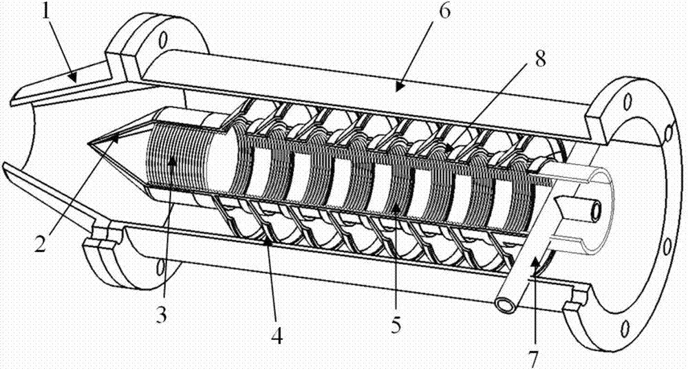
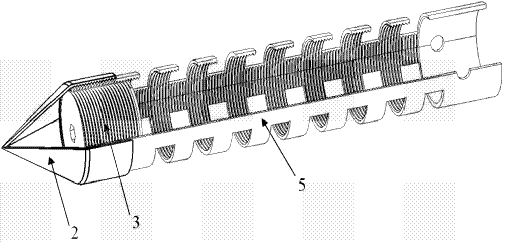
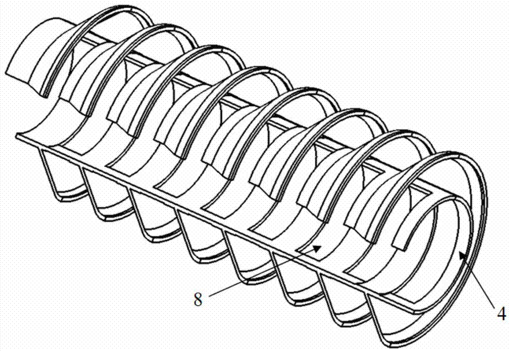
[0020] Such as Figure 4 As shown, the inner wall surface of the cylinder 5 of the anti-reflux intake structure of the air-breathing pulse detonation engine in this embodiment is processed with internal threads, and the adjustable inner plug 3 is installed in the cylinder 5 through threaded connection, and can be adjusted by The hexagonal hole at the end of the inner plug 3 adjusts the position of the plug in the cylinder 5. During the air intake process, the air enters the detonation chamber 11 through the air intake channel and the annular channel. Fuel is sprayed axially into the detonation chamber 11 through the fuel pipe 7 and mixed with air. After the igniter 10 is ignited and detonated, the backflow enters the cavity of the cylinder 5 against the direction of the incoming flow, and enters the annular cavity of the circular tube section 6 from the two rows of annular backflow grooves 8 in the inner cavity. The cylinder 4 guides the air flow, the direction of the revers...

Embodiment 2

[0022] Such as Figure 5 As shown, Venturi 9 is installed between the circular pipe section 6 of the anti-backflow air intake structure of the air-breathing pulse detonation engine of this embodiment and the connecting section of the detonation chamber 11, and the cross-sectional area of ​​its throat is the same as that of the cylinder 5 inner cavity. equal in cross-sectional area. First, the incoming flow at a certain speed enters the engine from the air inlet formed by the air intake housing 1 and the rectified air intake cone 2, enters the detonation chamber 11 after passing through the ring cavity formed by the guide fin cylinder 4 and the cylinder 5, and It is fully mixed and atomized with the fuel sprayed from the fuel pipe 7. When the detonation chamber 11 is filled, the igniter 10 starts to ignite, forming a slow wave that propagates to the outlet of the detonation chamber, and the slow wave is accelerated by the spiral intensifier 12 to form a detonation wave that pr...


PUM


Abstract

The invention discloses a structure for preventing backflow from entering an air intake duct of an air-breathing pulse detonation engine. The air intake duct of the engine is formed by an air intake housing and a rectification air intake cone. An annular passage is formed by a circular tube section and a cylinder. The rectification air intake cone is fixed to the cylinder. An adjustable inner plug is installed in the cylinder through threads. A diversion fin cylinder is arranged on the cylinder in a sleeved mode and fixed by the rectification air intake cone. The cylinder is fixed to the circular tube section through a fuel oil tube. Air enters a detonation chamber through the air intake duct and the annular passage, and fuel oil is axially sprayed into the detonation chamber through the fuel oil tube and mixed with the air. After ignition and detonation, the backflow enters an inner cavity of the cylinder against the incoming flow direction, enters the annular passage formed by the circular tube section and the cylinder through two rows annular slotted holes of the inner cavity, the backflow changes the direction and interacts with backflow passing by the cylinder under the diversion action of the diversion fin cylinder on airflow, the total pressure of the backflow is gradually reduced, the flow rate of the backflow entering the air inlet duct is reduced, and therefore the propulsion performance of the engine is greatly improved.

Description

technical field [0001] The invention belongs to the field of pulse detonation engines, and in particular relates to an air-breathing pulse detonation engine anti-backflow intake structure. Background technique [0002] The pulse detonation engine is a new concept propulsion device that uses high-temperature and high-pressure gas generated by periodic detonation waves to generate thrust. Because of its advantages of high thermal cycle efficiency and simple structure, it will become the most advanced power device in the future. The air-breathing pulse detonation engine uses the oxygen in the air as an oxidant to reduce the load of the aircraft and increase the range of the aircraft. During the working process of the air-breathing pulse detonation engine, the high-temperature and high-pressure gas generated after the detonation wave combustion will appear to be transmitted back. If the returned shock wave and gas enter the intake port, it will cause the pressure pulsation of ...

Claims


Application Information

Patent Timeline
Patent Type & Authority Applications(China)
IPC IPC(8): F02K9/60
Inventor 郑龙席卢杰王治武
Owner NORTHWESTERN POLYTECHNICAL UNIV
Why Eureka
Try Eureka