Backlight module

A technology of backlight module and light source, applied in the field of a large number of backlight modules, can solve problems such as increasing cost

Inactive Publication Date: 2014-06-25
HONG FU JIN PRECISION IND (SHENZHEN) CO LTD +1
View PDF5 Cites 12 Cited by
  • Summary
  • Abstract
  • Description
  • Claims
  • Application Information

AI Technical Summary

Problems solved by technology

However, the above structure requires the application of ...

Method used


Image

  • Backlight module
  • Backlight module
  • Backlight module

Examples


Embodiment Construction

[0014] The present invention will be further described below with reference to the drawings.

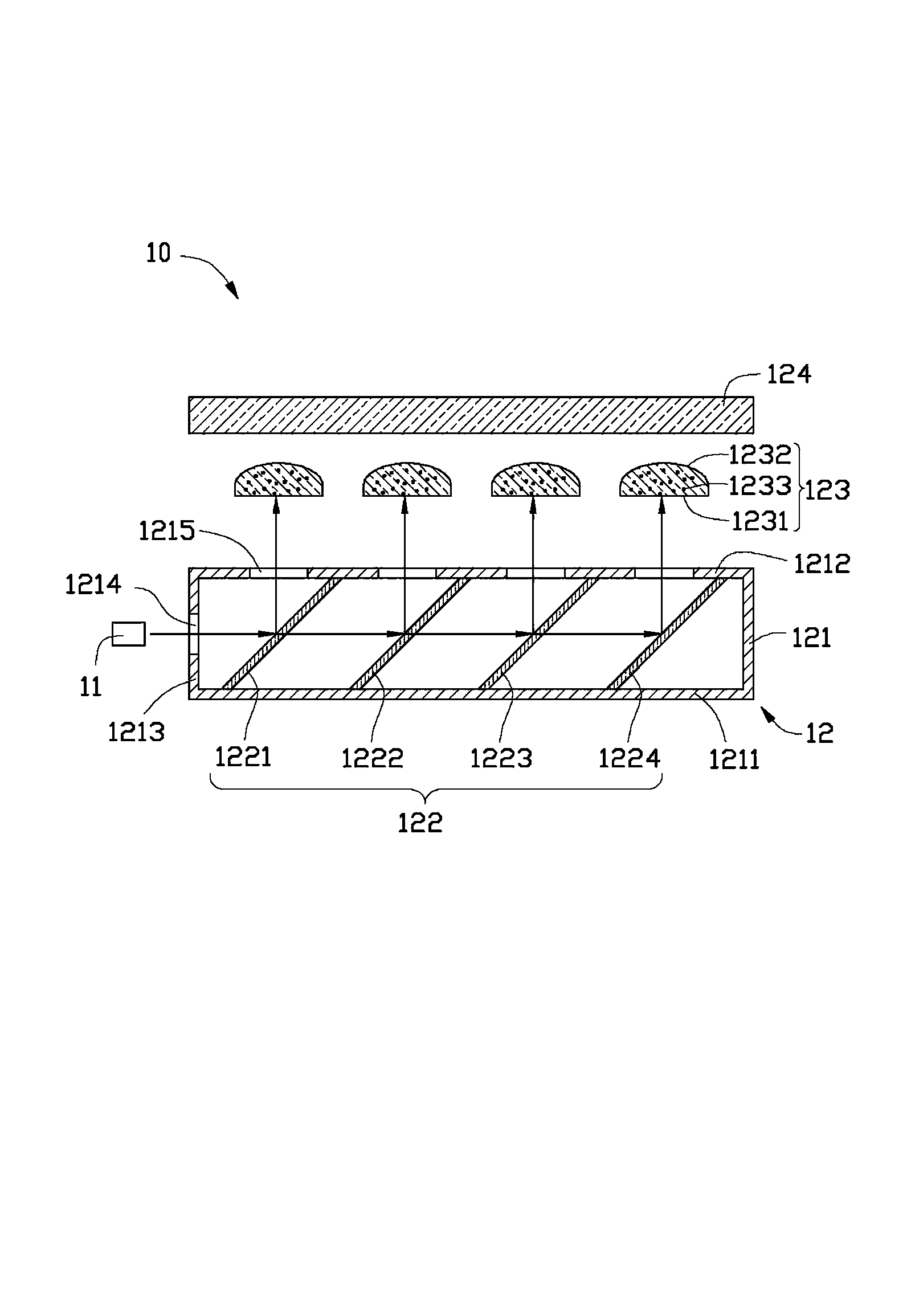
[0015] See figure 1 , the backlight module 10 provided by the first embodiment of the present invention includes a light source 11 and a light guide plate 12 .

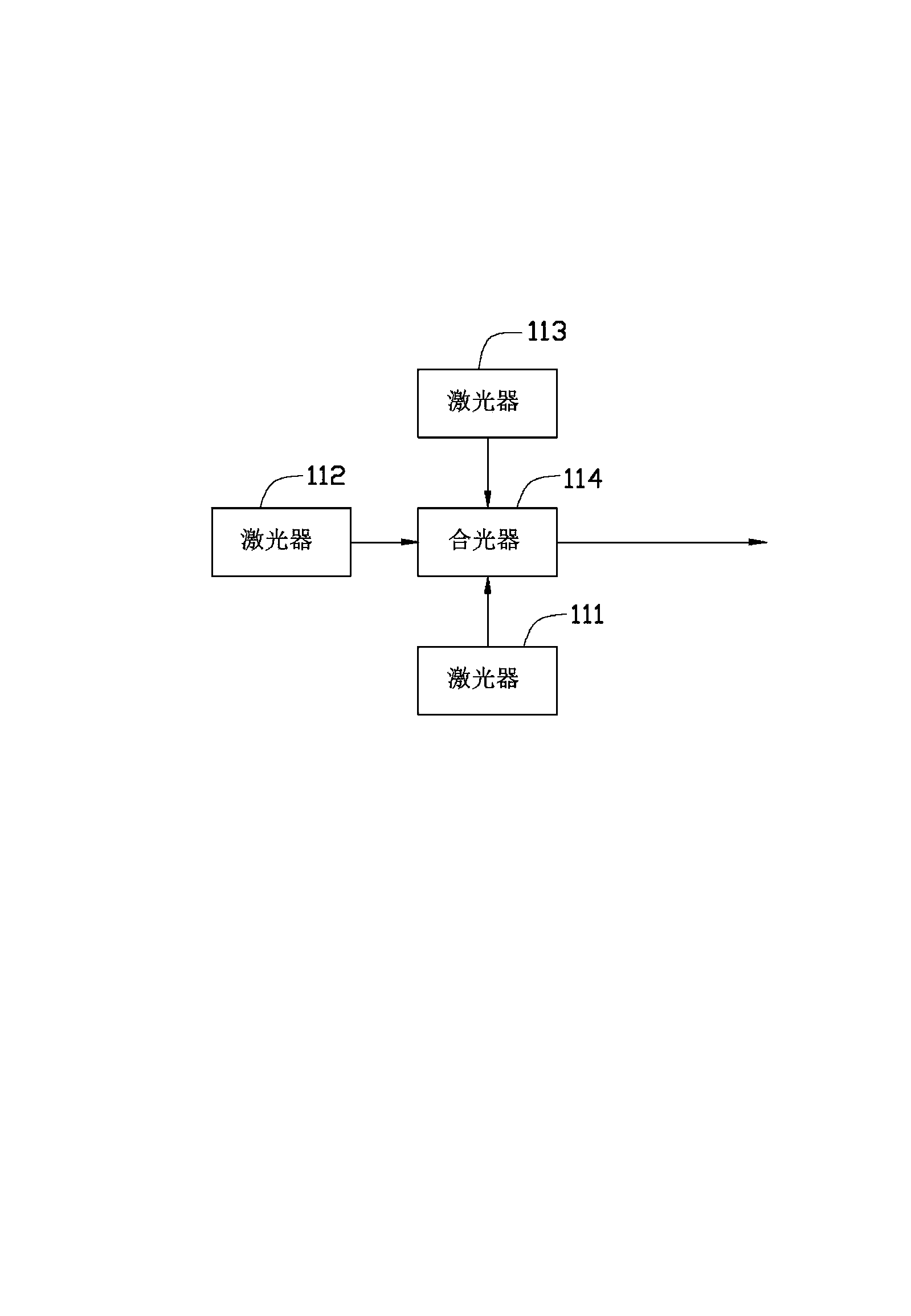
[0016] The light source 11 is arranged on the side of the light guide plate 12 , and the light emitted by the light source 11 is incident from the side of the light guide plate 12 and then exits from the upper surface of the light guide plate 12 . In this embodiment, the light source 11 is a laser light source. According to requirements, the light source 11 includes a first laser light source 111 , a second laser light source 112 , a third laser light source 113 and a light combining prism 114 . See figure 2 , the first laser light source 111 emits red laser light, the second laser light source 112 emits green laser light, and the third laser light source 113 emits blue laser light. The light emitted by the first laser ...


PUM


Abstract

A backlight module comprises a light source and a light guide plate. The light source is disposed on one side of the light guide plate. The light guide plate is provided with a plurality of semi-permeable semi-reflecting films. The semi-permeable semi-reflecting films are arranged at intervals along the light emergence direction of the light source. Each semi-permeable semi-reflecting film is provided with a light scattering element. When light from the light source enters the semi-permeable semi-reflecting films, part of the light passes the semi-permeable semi-reflecting films and continues to move in the original direction, and the other part of the light is reflected by the semi-permeable semi-reflecting films and enters the outside from the light scattering elements. Only one light source enables the backlight module to emit a row of light, so that fewer light sources are used in the backlight module.

Description

technical field [0001] The invention relates to a backlight module, in particular to a backlight module capable of reducing the number of light sources. Background technique [0002] A light emitting diode (Light Emitting Diode, LED) is an optoelectronic semiconductor element that can convert current into a specific wavelength range. Light-emitting diodes can be widely used as light sources in the field of lighting because of their advantages such as high brightness, low operating voltage, low power consumption, easy matching with integrated circuits, simple driving, and long life. [0003] The light emitting diode can be used in the backlight module as the light source of the backlight module. Generally, a plurality of light emitting diodes are arranged in an array shape, and then a diffusion plate is arranged on the plurality of light emitting diodes to adjust the light distribution thereof. However, the above-mentioned structure needs to use more light-emitting diode el...

Claims


Application Information

Patent Timeline
IPC IPC(8): F21S8/00F21V8/00F21V13/02
Inventor 陈柏洲
Owner HONG FU JIN PRECISION IND (SHENZHEN) CO LTD
Why Eureka
Try Eureka