
Isolation circuit having Hall element and oscilloscope of isolation circuit
A Hall element and isolation circuit technology, applied in instruments, measuring electrical variables, digital variables/waveform display, etc., can solve problems such as raising high frequency, uneven frequency response, complex low frequency path circuit, etc., and achieve high DC accuracy , high voltage isolation, and simple circuit form
- Summary
- Abstract
- Description
- Claims
- Application Information
AI Technical Summary
Problems solved by technology
Method used
Image

Examples
Embodiment 1
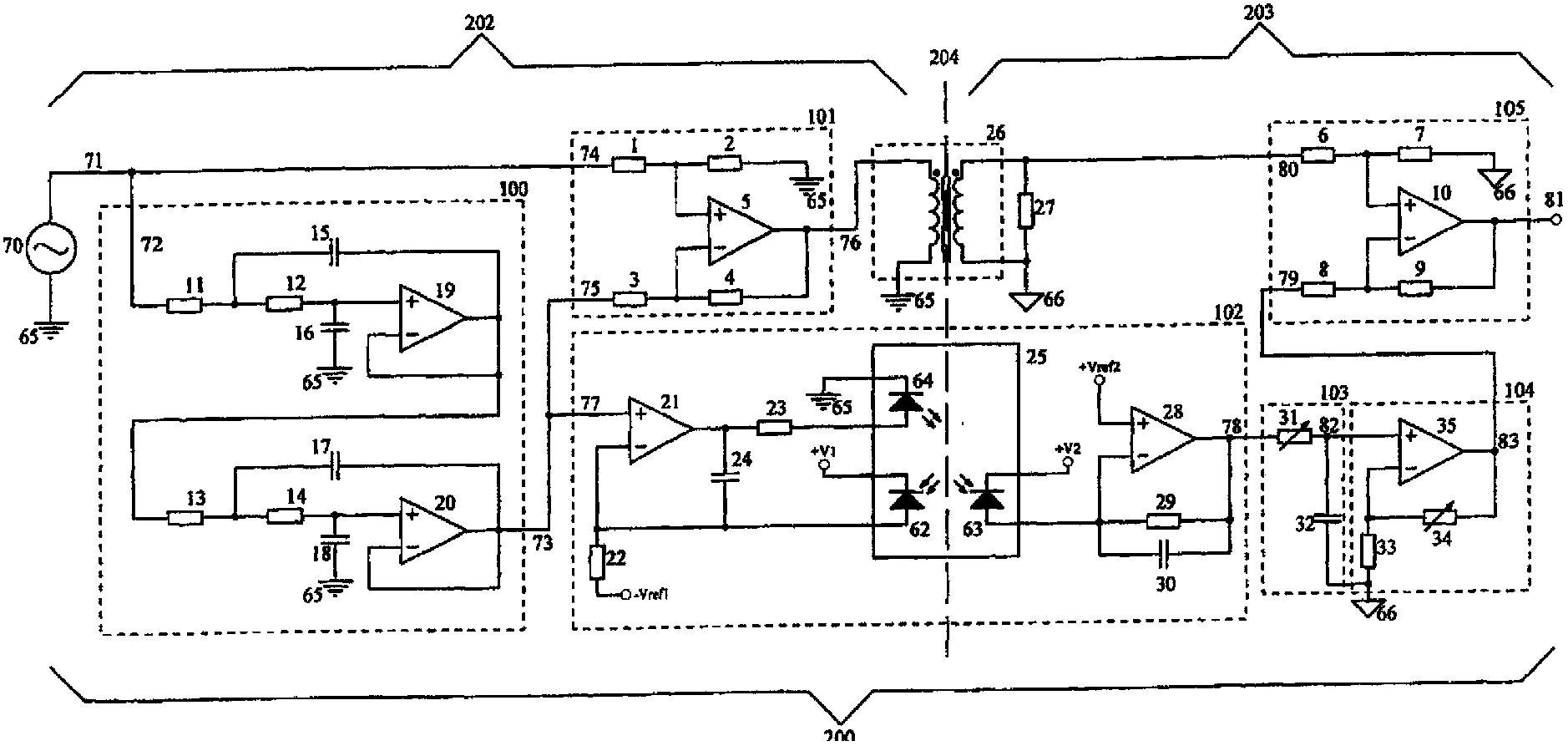
[0104] Figure 10 It is a schematic diagram of the structure of this embodiment. This embodiment is applicable to the application of single-ended signal input and single-ended signal output.
[0105] As shown in the figure, the buffer circuit is specifically a follower circuit composed of an operational amplifier. The buffer circuit U1 meets the bandwidth index of the linear isolation circuit design and needs to amplify the input current to be able to drive the primary winding of the transformer.
[0106] The buffer and the second amplifier can be any high-speed amplifier, as long as it can meet the maximum bandwidth and maximum voltage amplitude required by the design. Of course, choosing a larger bandwidth, low noise, and low distortion amplifier can help realize the design bandwidth requirements. For example, AD8038 and AD8012 of ADI Company.
[0107] In this implementation, the transformer adopts a common transformer winding method, that is, the primary winding and the ...
Embodiment 2
[0112] Figure 11 It is a schematic diagram of the structure of this embodiment.
[0113] The difference between this embodiment and Embodiment 1 is that the transformer is wound in a different way.
[0114] For the transformer in this embodiment, in order to achieve a bandwidth as large as possible, the minimum operating frequency needs to be extended to less than 10 kHz, and the maximum operating frequency should be greater than the designed bandwidth. Moreover, the withstand voltage between the primary line combination and the secondary line group must meet the design expectations. In this embodiment, the transformer winding method adopts the transmission line transformer method, which can achieve better frequency response. Other forms of transformers can also be implemented, but the frequency response is slightly worse.
[0115] The best choice for transformer magnetism is high permeability soft ferrite magnetic ring, such as the R10K series of Beijing Qixing Flying Ele...
Embodiment 3
[0119] Figure 12 It is a schematic structural diagram of this embodiment, which is applied when the input signal is a differential input.
[0120] The difference between this embodiment and Embodiment 1 is that the buffer circuit is a circuit composed of a fully differential amplifier.
[0121] As shown in the figure, the differential signal input is Vin_P and Vin_N, the fully differential amplifier input feedback resistor R1=R2=R3=R4, and the amplifier differential output is used to drive both ends of the primary winding.
[0122] The fully differential operational amplifier needs to meet the bandwidth requirements of the linear isolation circuit design. In this implementation, LMH6554 from TI or ADA4937 from Analog Devices is preferred, and the input and feedback resistors are 300Ω.
PUM
 Abstract
Description
Claims
Application Information