A material pasting device for a display device

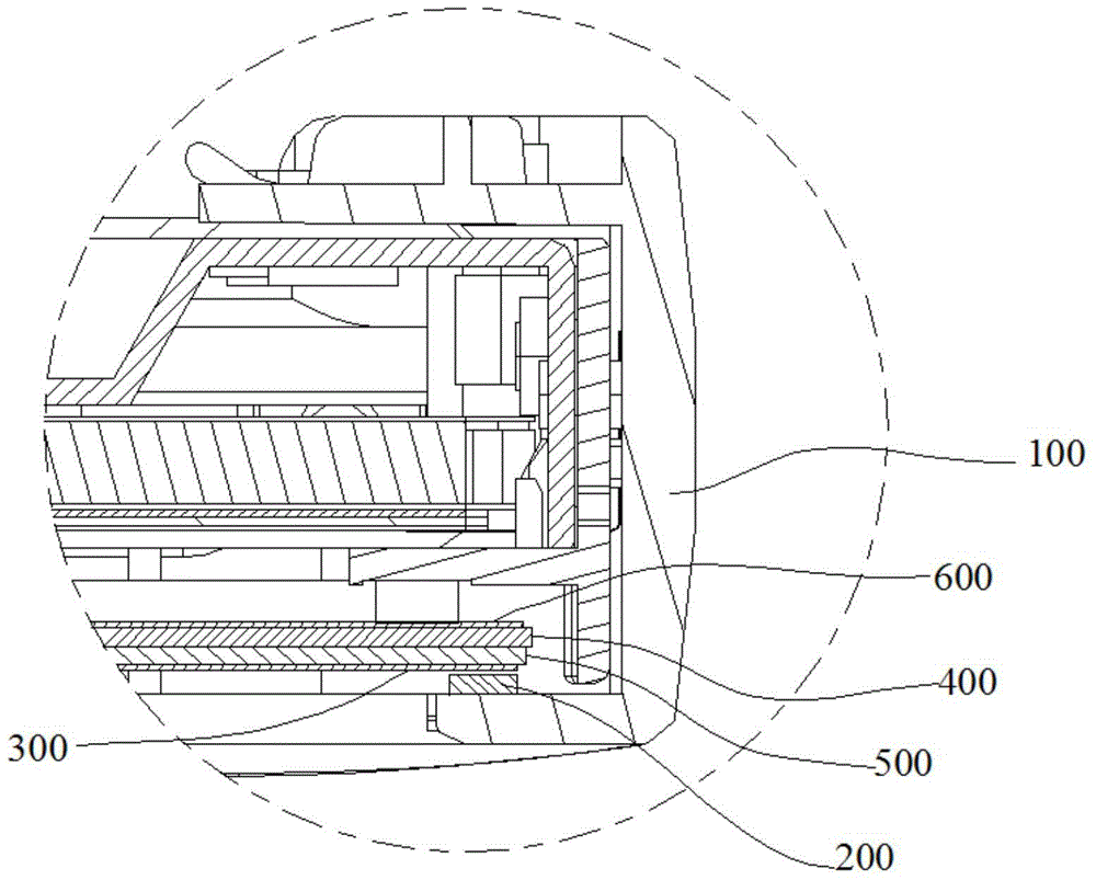
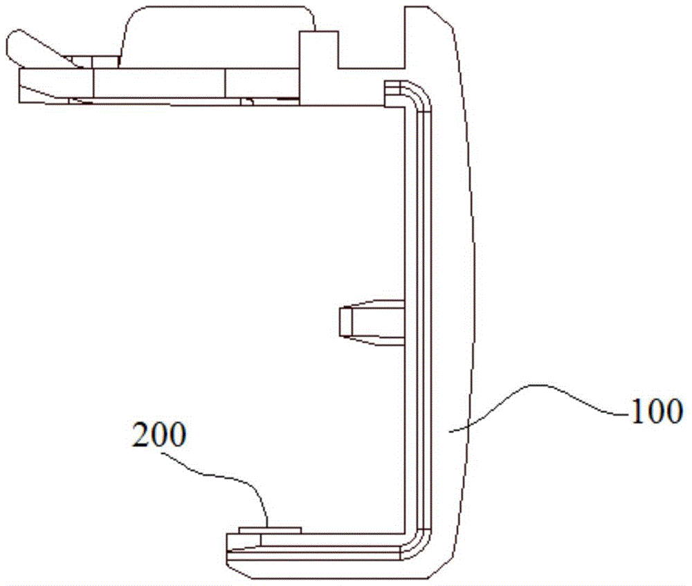
A technology of a sticking device and a display device, which is applied in nonlinear optics, instruments, optics, etc., can solve the problems that the human eye cannot see the sticking position of the seal 200, the image quality is poor, and it is difficult to ensure the installation accuracy.

Active Publication Date: 2016-06-22
HISENSE VISUAL TECH CO LTD
View PDF4 Cites 0 Cited by
  • Summary
  • Abstract
  • Description
  • Claims
  • Application Information

AI Technical Summary

Problems solved by technology

[0003] At present, the front shell of the LCD TV integrated with the screen shell is usually U-shaped, such as figure 1 As shown, the U-shaped front case 100 is directly coated on the edge of the LCD TV to fix components such as the liquid crystal panel 300 of the LCD TV, so that the U-shaped front case 100 plays the role of the outer frame of the liquid crystal panel 300, thus eliminating the need for It is the metal frame of the liquid crystal panel 300 itself, which reduces the thickness of the LCD TV, but if the U-shaped front shell 100 is in direct contact with the liquid crystal panel 300, the U-shaped front shell 100 may scratch the liquid crystal in the event of vibration and extrusion. panel 300, thereby causing irreparable damage to the liquid crystal panel 300 and affecting the display effect. At the same time, due to the gap between the U-shaped front case 100 and the liquid crystal panel 300, the light passing through the reflector 600, the prism group 400 and the light guide plate 500 may be It leaks from the gap between the U-shaped front case 100 and the liquid crystal panel 300, resulting in poor image quality. Therefore, the U-shaped front case must be pasted with a sealing member 200 when in use. Since the sealing member 200 is soft, it can be attached to the liquid crystal panel 300 respectively. It is attached to the U-shaped front shell 100, thereby eliminating the gap between the liquid crystal panel 300 and the U-shaped front shell 100, and providing a buffer for the U-shaped front shell 100 and the liquid crystal panel 300, preventing the U-shaped front shell 100 from wearing the liquid crystal panel 300, To avoid damage to the LCD panel and adverse effects on image quality, and in order to obtain a better sealing effect, the installation of the seal should ensure high precision to avoid friction and light leakage to the greatest extent
[0004] In the prior art, for the U-shaped front shell of LCD TV, which needs to be pasted with seals but the operating space is limited, the problems of pasting the seals are as follows: figure 2 and image 3 As shown, when installing in a vertical viewing angle, since the sticking position of the seal 200 is on the inner side of the U-shaped front shell 100, the operator's line of sight is blocked, and the sticking position of the seal 200 cannot be seen by the human eye, making the operation difficult. When installing under a horizontal viewing angle, since there is no positioning surface on the inner side of the U-shaped front shell 100 for the seal to stick, it is difficult to ensure the installation accuracy

Method used


Image

  • A material pasting device for a display device
  • A material pasting device for a display device
  • A material pasting device for a display device

Examples


Embodiment Construction

[0036] The following will clearly and completely describe the technical solutions in the embodiments of the present invention with reference to the accompanying drawings in the embodiments of the present invention. Obviously, the described embodiments are only some, not all, embodiments of the present invention. Based on the embodiments of the present invention, all other embodiments obtained by persons of ordinary skill in the art without making creative efforts belong to the protection scope of the present invention.

[0037]In describing the present invention, it is to be understood that the terms "center", "upper", "lower", "front", "rear", "left", "right", "vertical", "horizontal", The orientations or positional relationships indicated by "top", "bottom", "inner", "outer", etc. are based on the orientations or positional relationships shown in the drawings, and are only for the convenience of describing the present invention and simplifying the description, rather than ind...


PUM


Abstract

The embodiment of the invention provides a material pasting device for a display device, and relates to the technical field of liquid crystal display. The device reduces difficulty of material pasting and improves the pasting precision of the materials. The material pasting device for the display device comprises a base, a sliding support and a sealing brush. A mounting groove for containing a part of to-be-pasted materials of the display device is formed in the base, the sliding support is erected on the base and is in sliding connection with the base, the sliding direction of the sliding support is consistent with the pasting direction of the to-be-pasted materials, the sealing brush comprises a brush handle connected with the sliding support and a brush head arranged at one end of the brush handle, a press-fit face is arranged on the side, facing the to-be-pasted materials of the part, of the brush head, and a limiting groove for limiting the materials is formed in the brush head. The material pasting device for the display device is used for pasting materials for the display device.

Description

technical field [0001] The invention relates to the technical field of liquid crystal display, in particular to a material pasting device for a display device. Background technique [0002] With the development of the LCD TV industry, the development trend of the LCD TV frame is narrower and thinner. The emergence of LCD TVs with integrated screen and shell meets the needs of narrow and thin LCD TVs. This technology can integrate the front shell with the LCD module. The integration into one body saves the metal frame of the common liquid crystal module and makes the liquid crystal TV narrower and thinner. [0003] At present, the front shell of the LCD TV integrated with the screen shell is usually U-shaped, such as figure 1 As shown, the U-shaped front case 100 is directly coated on the edge of the LCD TV to fix components such as the liquid crystal panel 300 of the LCD TV, so that the U-shaped front case 100 plays the role of the outer frame of the liquid crystal panel 30...

Claims


Application Information

Patent Timeline
Patent Type & Authority Patents(China)
IPC IPC(8): G02F1/13
Inventor 曹永强
Owner HISENSE VISUAL TECH CO LTD
Why Eureka
Try Eureka