
Lead and conductor connection device of strain gauge

A technology of wire connection and strain gauge, which is applied in the direction of flexible lead devices, measuring devices, clamping/spring connections, etc., can solve the problems of short circuit, disconnection of wires and terminals, unfavorable economic and environmental protection, etc., to prevent short circuit Phenomenon, prevent mutual crossing, avoid the effect of short circuit

Inactive Publication Date: 2016-06-29
QINGDAO TECHNOLOGICAL UNIVERSITY
View PDF5 Cites 4 Cited by
  • Summary
  • Abstract
  • Description
  • Claims
  • Application Information

AI Technical Summary

Problems solved by technology

However, in the process of sticking strain gauges in complex environments, there are often problems such as short circuits due to the small size and light weight of the strain gauges, the thinness and shortness of the two lead wires of the strain gauge, and the easy contact of the two lead wires, especially when When the pasting space of the strain gauge is narrow, the already cumbersome step of pasting the strain gauge becomes more difficult.
On the offshore ship operating platform, due to factors such as strong sea wind and light weight of strain gauges, many strain gauges are often lost in the actual process of sticking strain gauges, which is time-consuming and laborious, and the success rate of strain gauge sticking is low, which is not conducive to economy. Environmental protection. At the same time, when the strain gauge is pasted and connected to the wire, often due to the lack of solder in the terminal and the difficulty of hanging tin under the wire connection part, the welding is not so smooth.
Moreover, after the wires are connected to the terminals, the wires are often moved due to the needs of on-site wire pulling and wiring, which will cause the wires to be disconnected from the terminals, causing the strain gauge to fail

Method used


Image

  • Lead and conductor connection device of strain gauge
  • Lead and conductor connection device of strain gauge
  • Lead and conductor connection device of strain gauge

Examples


Embodiment

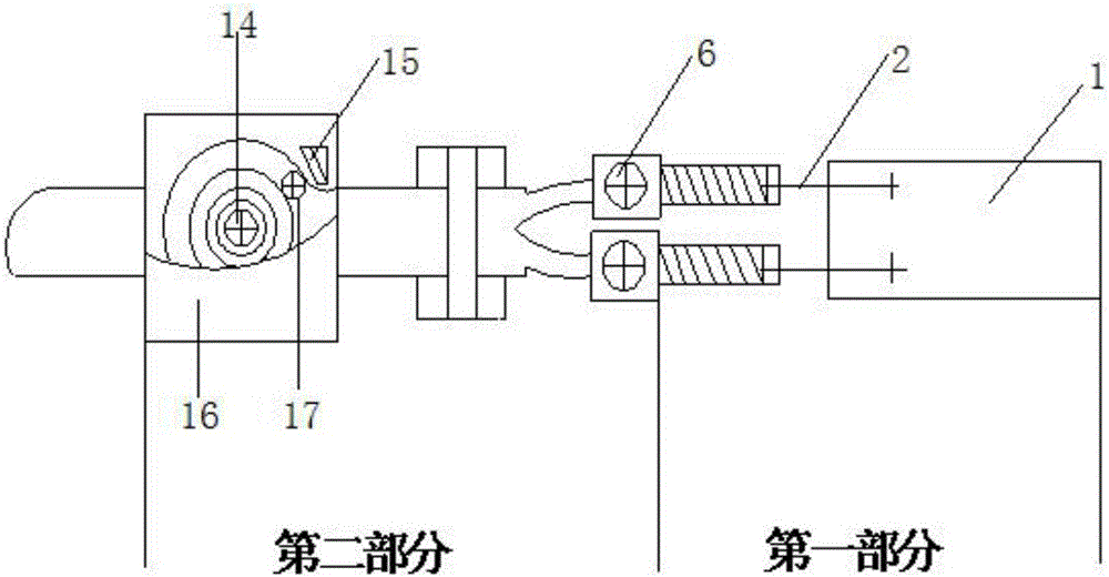
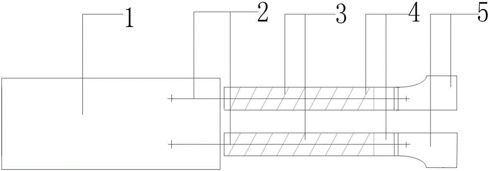
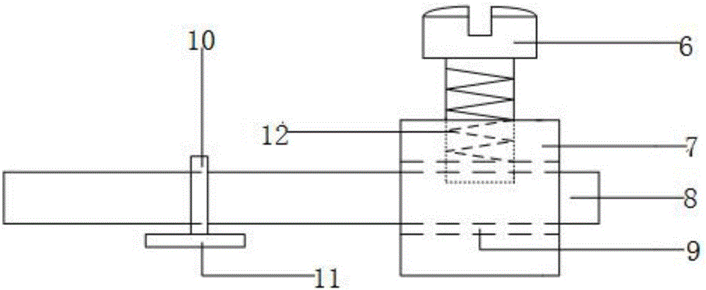
[0017] The main structure of this embodiment is composed of a strain gauge lead device (the first part) and a strain gauge lead and wire connection device (the second part). The strain gauge lead device includes a strain gauge 1, a lead 2, a translucent rectangular parallelepiped colloid 3, Double-sided tape 4, arc welding piece 5, strain gauge lead and wire connection device including half-round head cross bolt 6, fastening block 7, wire 8, wire through hole 9, fastening tape 10, adhesive sheet 11, threaded hole 12. Clockwork sheet 13, clockwork pin 14, lock 15, housing 16, and stop shaft 17; strain gauge 1 and two leads 2 are connected by two solder points on the upper surface of strain gauge 1; two leads 2 are connected by Two translucent rectangular parallelepiped colloids 3 are wrapped. The translucent rectangular parallelepiped colloid 3 has a certain degree of hardness (toughness) (cannot be broken at one time); the ends of the two leads 2 pass through a series of solder ...


PUM


Abstract

The invention belongs to the technical field of a test device, and relates to a lead and conductor connection device of a strain gauge. The strain gauge is connected with two leads; the tail ends of the two leads are connected with arched soldering lugs; the backs of semitransparent cuboid gels are double sticky tapes; the tail ends of the semitransparent cuboid gels are connected with the arched soldering lugs; the upper half part of a fastening block is equipped with a threaded hole; the threaded hole is connected with a cup head cross-recess bolt; a conductor through hole is opened in the middle part of the fastening block; insulation paint is coated on the lower surface of the fastening block; the upper end of the fastening block is a circular fastening belt; the lower part of the fastening belt is an adhering sheet; the adhering sheet penetrates the fastening belt; the conductor at the outer side of each ring of spring sheet is winded on the spring sheet; one end of the spring sheet is clamped on a spring clamping shaft; the other end is located at the lower outlet of the conductor; the spring clamping slot is connected with an upper enclosure and a lower enclosure; and a triangular prism-shaped lock catch and a blocking shaft are mounted at the lower outlet of the conductor. The device is simple in structure, scientific and reliable in principle, flexible and convenient in operation and regulation mode and wide in application prospect.

Description

Technical field: [0001] The invention belongs to the technical field of testing instruments, and relates to an improved equipment for the traditional strain gauge lead and an improved strain gauge lead and wire connection equipment, in particular to a strain gauge lead and wire connection device, which combines the strain gauge lead device and the strain gauge The sheet lead and the wire connection device are combined into an integrated structure, which is suitable for the simple and quick sticking of strain gauges and the connection of wires in most complex environments. Background technique: [0002] Strain gauge is the most commonly used sensor in industrial tests. Due to its high test accuracy, small size, light weight, and wide application range, strain gauges are widely used in various automatic control industries, involving water conservancy and hydropower, railway transportation, electric power, Shipbuilding, machine tools and many other industries. The strain gauge is c...

Claims


Application Information

Patent Timeline
IPC IPC(8): H01R11/11H01R4/36H01R13/72G01L1/22G01L9/04G01L23/18
CPCG01L1/22G01L9/04G01L23/18H01R4/36H01R11/11H01R13/72H01R2201/20
Inventor 张黎明蒋圣群郭秋丛宇丛怡王在泉
Owner QINGDAO TECHNOLOGICAL UNIVERSITY
Learn More