
Finite element modeling method of thermal barrier coating of turbine blade with multiple cooling channels

A technology for cooling channels and turbine blades, applied in special data processing applications, instruments, electrical digital data processing, etc., can solve the problems of small thickness of TGO layer, lack of geometric model size, geometric model does not take into account the real shape of the tenon, etc.

Active Publication Date: 2014-06-25
XIANGTAN UNIV
View PDF2 Cites 5 Cited by
  • Summary
  • Abstract
  • Description
  • Claims
  • Application Information

AI Technical Summary

Problems solved by technology

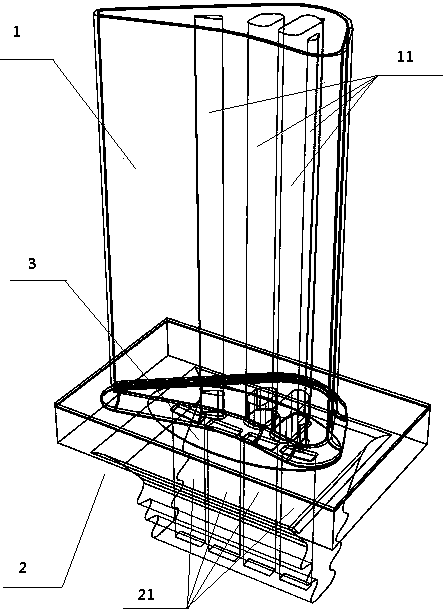
Although this method solves certain problems, with the continuous progress and improvement of scientific research level, this method shows obvious shortcomings and disadvantages: first, the construction of its geometric model needs to be carried out in CATIA software, and then the geometric model Import it into the finite element software ABAQUS for related simulation calculations. For the complex model of the thermal barrier coating of turbine blades, because the relative thickness of the TGO layer is very small, it will cause geometric problems due to the different accuracy requirements between the software. The lack of model size leads to the mismatch between the various parts of the model, so the secondary processing of the geometric model is necessary for subsequent calculations, and the establishment of the model requires the modeler to be proficient in CATIA software and ABAQUS software Second, the construction of the geometric model did not take into account the real shape of the tenon, let alone the multiple cooling channels of the turbine blade in the actual situation. The airfoil part of the model in the invention patent There is only one channel, and the underside of the blade body is a solid cuboid, not a tenon of actual shape, so the only channel is essentially impassable

Method used


Image

  • Finite element modeling method of thermal barrier coating of turbine blade with multiple cooling channels
  • Finite element modeling method of thermal barrier coating of turbine blade with multiple cooling channels
  • Finite element modeling method of thermal barrier coating of turbine blade with multiple cooling channels

Examples


Embodiment 1

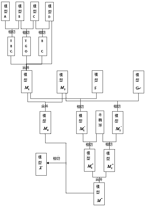
[0088] Select the single turbine blade model that has been established as the implementation object, and use the finite element software ABAQUS to establish the finite element model, mainly to carry out its finite element simulation under thermal cycle load.

[0089] For the sake of convenience and simplification, the present invention makes the following assumptions: 1) The material of each layer of TBCs is isotropic; 2) The thickness of each layer of TBCs is uniform; 3) The ideal elastic-plastic model is adopted; 4) The creep of each layer is a time-hardening model.

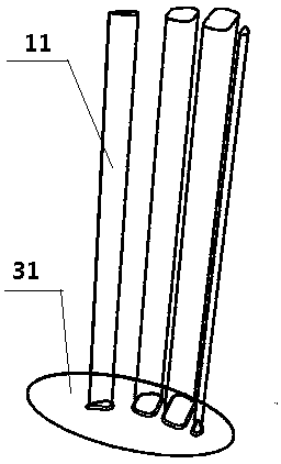
[0090] The finite element modeling method of turbine blade thermal barrier coating with multiple cooling channels includes the following steps:

[0091] 1. Construction of geometric model of turbine blade without cooling channel

[0092] (1) Establishment of the geometric model of the blade body

[0093] (1) The establishment of the geometric model in the early stage

[0094] In the geometric model, the ther...


PUM


Abstract

The invention relates to a finite element modeling method of a thermal barrier coating of a turbine blade with multiple cooling channels. The finite element modeling method includes the steps of firstly, modeling a whole turbine blade without the cooling channels, wherein the particular modeling process includes the steps of tenon modeling and blade body modeling; then building a geometric model of the turbine blade with the multiple cooling channels, wherein the modeling process includes the steps of modeling a blade body part with the multiple cooling channels, modeling a tenon part with the multiple cooling channels and connecting the two models. The finite element modeling method is completely carried out in finite element software ABAQUS, and the problem of mismatching, caused by incomplete compatibility of multiple pieces of software, between parts is solved; in addition, the true shape of a tenon and the practical condition that the turbine blade is provided with the multiple cooling channels are considered during building of the geometric model, the built finite element model of the thermal barrier coating of the turbine blade is close to the practical condition, and computing results of follow-up temperature field and stress field analysis are accurate.

Description

technical field [0001] The invention relates to the technical field of a high-performance aeroengine turbine blade thermal barrier coating system, in particular to a finite element modeling method for a turbine blade thermal barrier coating containing multiple cooling passages. Background technique [0002] The material of turbine blades is the basis for ensuring the safe use of turbine engines, and it is an extremely important development field in contemporary material science and engineering. In order to meet the requirements of gas turbine engines, some countries have developed many kinds of ultra-high temperature alloy materials. However, directionally solidified alloys and single crystal alloys can only be applied to 1100 o C, it can't meet the needs of the current engine operating temperature, and the limit operating temperature of the turbine blades of the gas turbine is as high as 1650 o c. Based on this situation, people put forward the concept of thermal barrie...

Claims


Application Information

Patent Timeline
IPC IPC(8): G06F17/50
Inventor 杨丽李晓军周益春朱旺蔡灿英
Owner XIANGTAN UNIV
Learn More