Distributed Power Generation System and Its Remote Monitoring System

A remote monitoring system and distributed power generation technology, applied in information technology support systems, electrical components, circuit devices, etc., can solve problems such as unrealizable, reverse acquisition, and display of data information, so as to save time and cost, and reduce data The effect of volume and cost saving

Active Publication Date: 2016-05-18
ALTENERGY POWER SYST
View PDF4 Cites 0 Cited by
  • Summary
  • Abstract
  • Description
  • Claims
  • Application Information

AI Technical Summary

Problems solved by technology

[0004] It can be seen that the existing technology requires the communicator 105 to connect to the Internet 106 through the network port device 103, otherwise it cannot have such a remote monitoring function, and some customers do not have the network port device 103, so this function cannot be realized
In addition, the account information and other data of the monitoring terminal 108 are only stored in the database 107, and other devices such as the communicator 105 do not have the account information of the monitoring terminal 108, which is inconvenient for customers to use, and it will be troublesome if customers forget it.
In addition, in the prior art, the communicator 105 transmits the operating data to the database 107 in one direction, without reversely obtaining and displaying data information from the database 107, especially when the communicator 105 is not connected to the Internet 106

Method used


Image

  • Distributed Power Generation System and Its Remote Monitoring System
  • Distributed Power Generation System and Its Remote Monitoring System
  • Distributed Power Generation System and Its Remote Monitoring System

Examples


Embodiment Construction

[0045] The present invention will be further described below in conjunction with specific embodiment and accompanying drawing, set forth more details in the following description so as to fully understand the present invention, but the present invention can obviously be implemented in many other ways different from this description, Those skilled in the art can make similar promotions and deductions based on actual application situations without violating the connotation of the present invention, so the content of this specific embodiment should not limit the protection scope of the present invention.

[0046] An embodiment of a remote monitoring system for a distributed power generation system

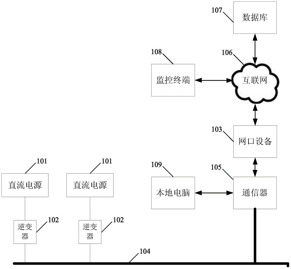
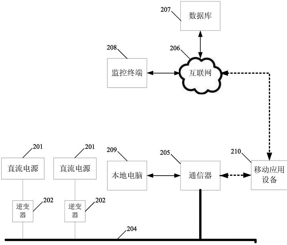
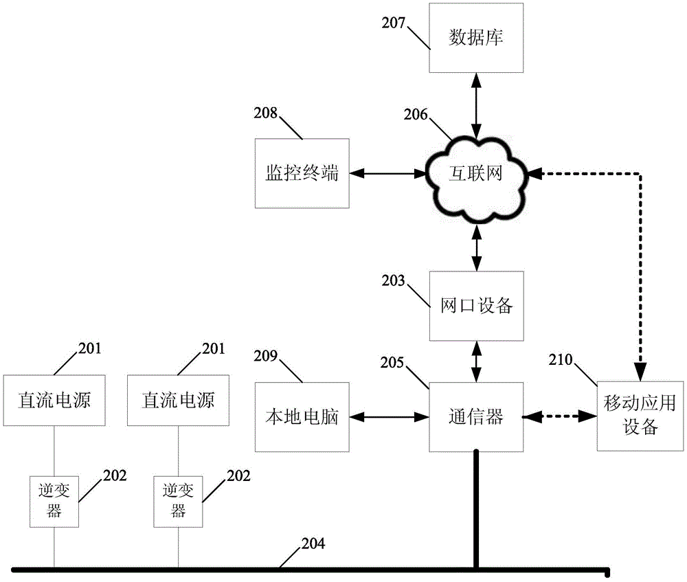
[0047] figure 2 It is a schematic diagram of modules connecting the distributed power generation system and its remote monitoring system according to an embodiment of the present invention. It should be noted that this and other subsequent drawings are only examples, and should not ...


PUM


Abstract

The invention provides a remote monitoring system for a distributed power generation system, the power generation system includes one or more DC power supplies and matching inverters, communicators and databases; the inverters are connected to bus cables; one end of the communicators It is connected to the bus cable, and the other end is connected to the database through the Internet; the remote monitoring system includes a monitoring terminal, a local computer and a mobile application device; the mobile application device and the communicator are connected through a local area wireless communication network, and through a wide area mobile communication network Connect to the database through the Internet; the monitoring terminal is also connected to the database through the Internet to obtain monitoring data; the local computer is connected to the communicator to make related settings on the communicator and display relevant information in the communicator. The invention establishes a two-way transmission and information display mechanism between the communicator and the database, can be connected without a network port device, and can accept remote monitoring. In addition, the information in the database can be sent back to the communicator and displayed, which is convenient for customers to use.

Description

technical field [0001] The invention relates to the technical field of monitoring of power generation systems, in particular, the invention relates to a distributed power generation system and a remote monitoring system thereof. Background technique [0002] In the existing distributed power generation system, the power generation unit (DC power supply and inverter) is connected to the communicator to transmit data, and the communicator is connected to the Internet to transmit the data to the database, thereby providing monitoring account usage and realizing remote monitor. [0003] figure 1 It is a schematic diagram of a module connected to a distributed power generation system and its monitoring terminal in the prior art. Such as figure 1 As shown, the power generation system includes multiple DC power sources 101 and their associated inverters 102 , network port equipment 103 , communicator 105 , database 107 and local computer 109 . Wherein, each inverter 102 is conn...

Claims


Application Information

Patent Timeline
Patent Type & Authority Patents(China)
IPC IPC(8): H02J13/00
CPCY04S10/40Y04S40/128Y02E60/00
Inventor 罗宇浩何赟一周懂明
Owner ALTENERGY POWER SYST
Why Eureka
Try Eureka