
Composite-magnetic-pole electromagnetic iron remover

An iron remover, electromagnetic technology, applied in the direction of magnetic separation, chemical instruments and methods, solid separation, etc., can solve the problem of being unable to be sucked up at the same time, when one end is sucked up, the other end is supported, electromagnetic iron remover Can not work normally, can not meet the on-site operation and other problems, to achieve the effect of simple structure, low maintenance cost, low manufacturing cost

Inactive Publication Date: 2014-07-02
FUSHUN KAIYU MECHANICAL & ELECTRICAL EQUIP
View PDF5 Cites 2 Cited by
  • Summary
  • Abstract
  • Description
  • Claims
  • Application Information

AI Technical Summary

Problems solved by technology

However, the electromagnetic iron remover has a big disadvantage, that is, when there are large ferromagnetic impurities in the material, it is difficult to absorb due to the limitation of the magnetic field strength and range, so that the electromagnetic iron remover cannot work smoothly.
Especially when there are long ferromagnetic sundries, both ends of the long piece cannot be sucked up at the same time. While one end is being sucked up, the other end is supported on the belt conveying the material, which is very easy to scratch the conveyor belt. Phenomenon
Cause damage to the conveyor belt and affect normal production, and even lead to serious consequences of production stoppage
Its scope of use is greatly limited and cannot meet the needs of on-site operations

Method used


Image

  • Composite-magnetic-pole electromagnetic iron remover
  • Composite-magnetic-pole electromagnetic iron remover
  • Composite-magnetic-pole electromagnetic iron remover

Examples


Embodiment Construction

[0014] The technical scheme of the present invention will be further described in detail below in conjunction with the drawings and specific embodiments.

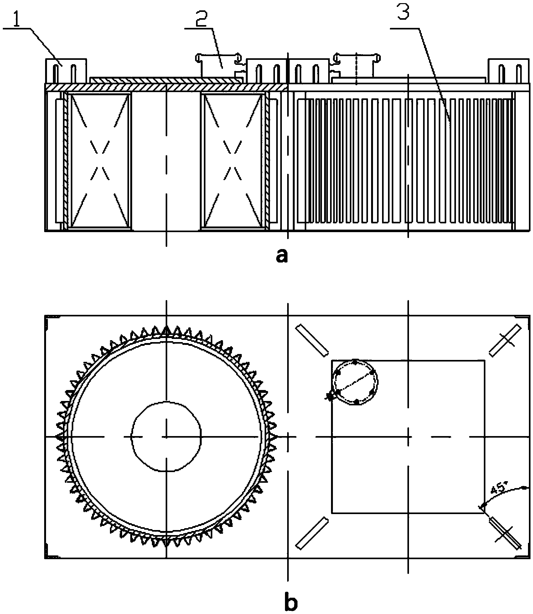
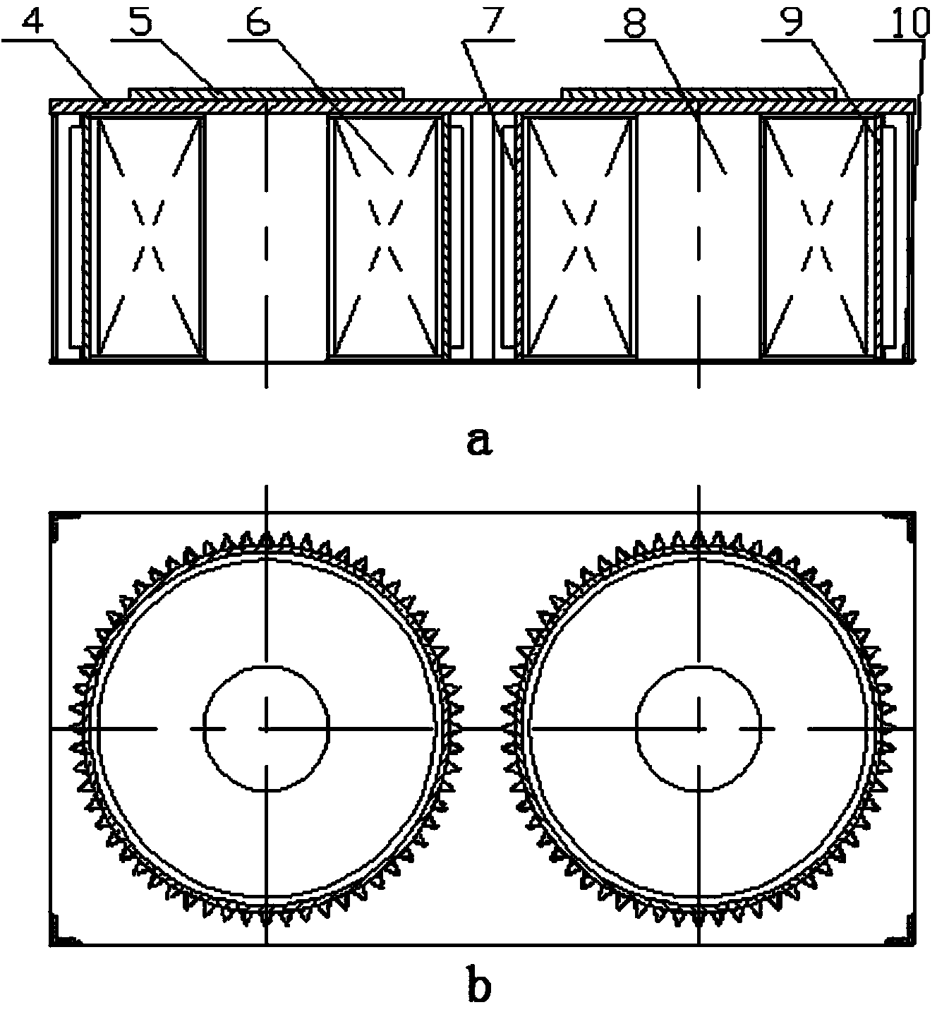
[0015] Reference Figure 1-Figure 2 , A composite magnetic pole electromagnetic separator includes a junction box 1, a lifting lug 2 and a magnetic system 3. The magnetic system part is composed of coil 6, iron core 8, cylinder 7, heat sink 9, large yoke plate 4, small yoke plate 5 and bottom plate 10. And it consists of two sets of coils, two iron cores and two cylinders. The junction box part uses two junction boxes corresponding to two sets of coils. The magnetic system is controlled by the electric control box through two junction boxes. Used in conjunction with metal detectors. The two sets of coils of the composite magnetic pole electromagnetic separator can work simultaneously, and the two coils can work independently.

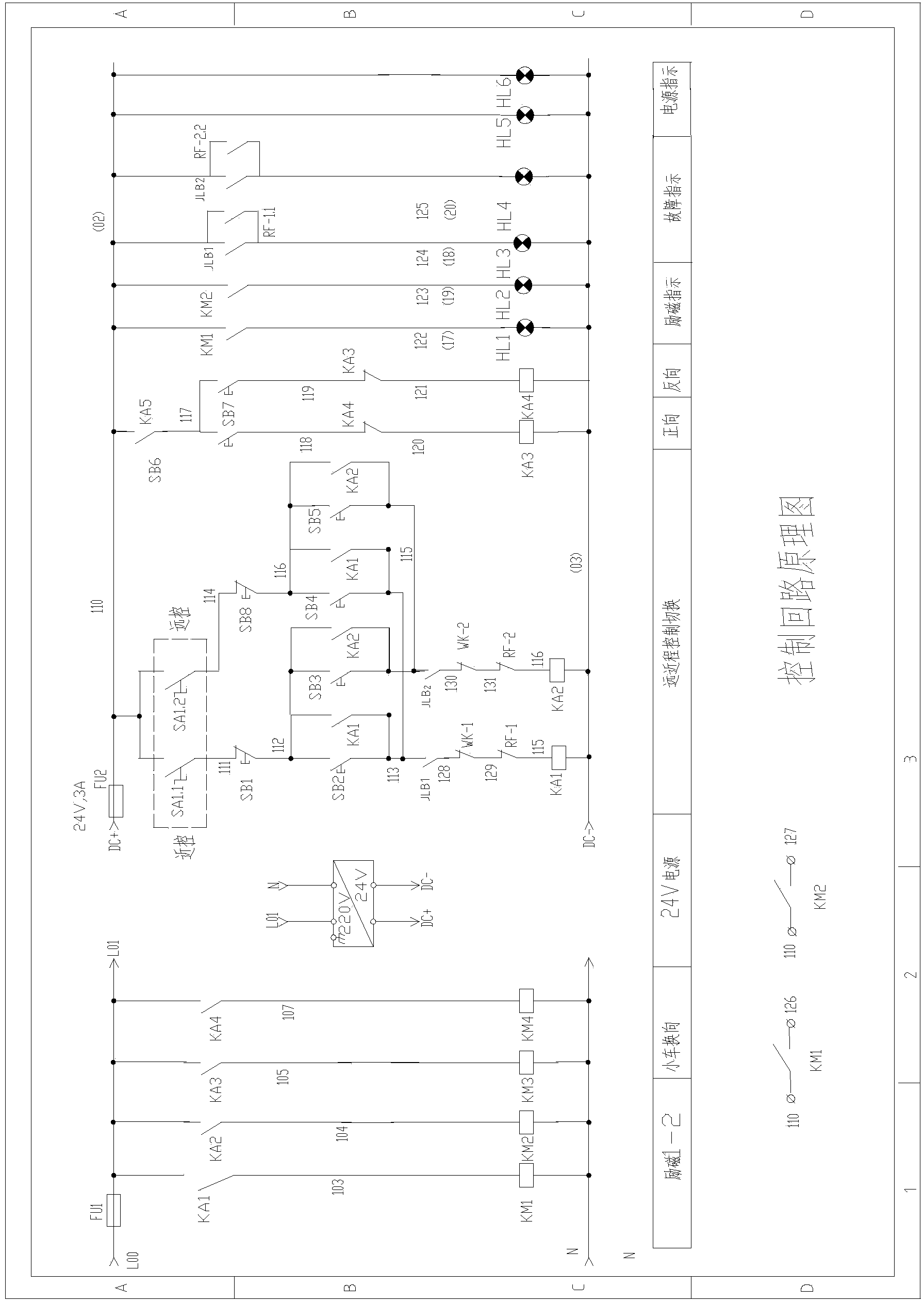
[0016] The electric control box for the composite magnetic pole electromagnetic separator, and it...


PUM


Abstract

The invention discloses a composite-magnetic-pole electromagnetic iron remover which is composed of a junction box (1), a lifting lug (2) and a magnetic system (3), wherein the magnetic system (3) is formed by sequentially connecting coils (6), an iron core (8), a cylinder (7), a cooling fin (9), a big yoke plate (4), a small yoke plate (5) and a bottom plate (10). The strength of a magnetic field is enhanced, the range of the magnetic field is widened, and therefore, the adsorption capacity is greatly improved. The composite-magnetic-pole electromagnetic iron remover can successfully absorb relatively large and relatively long ferromagnetic impurities so as to achieve the purpose that the ferromagnetic impurities in materials in a variety of conditions can be removed. The two sets of coils of the composite-magnetic-pole electromagnetic iron remover can work at the same time and can also independently work. On one hand, when a metal detector sends a signal for presenting that the relatively large or relatively long ferromagnetic impurities exist, the two coils are adopted for delivery of current at the same time; the strength of the magnetic field is enhanced, the range of the magnetic field is widened, the adsorption capacity is improved, and the relatively large or relatively long ferromagnetic impurities can be successfully absorbed; the smoothness of iron removal is realized; on the other hand, in general, a signal coil is adopted for the delivery of current, and therefore, energy is saved.

Description

Technical field [0001] The invention relates to an iron separator, in particular to a composite magnetic pole electromagnetic separator. Background technique [0002] The iron separators on the market today are divided into electromagnetic separators and permanent magnet separators according to the excitation method. Electromagnetic separators have low manufacturing cost, good performance, simple structure, convenient operation, stable and reliable operation, and wide application. However, the electromagnetic separator has a major drawback, that is, when there are large ferromagnetic debris in the material, it is difficult to adsorb due to the limitation of the magnetic field strength and range, which causes the electromagnetic separator to not work smoothly and normally. Especially when there are long ferromagnetic debris, both ends of the long piece cannot be sucked up at the same time. While one end is sucked up, the other end is supported on the material conveying belt, which...

Claims


Application Information

Patent Timeline
Patent Type & Authority Applications(China)
IPC IPC(8): B03C1/23
Inventor 崔雪桂晓祥李心宇马有利潘明学
Owner FUSHUN KAIYU MECHANICAL & ELECTRICAL EQUIP
Learn More