Forming method and die of anisotropic annular magnet

A ring magnet and anisotropic technology, which is applied in the manufacture of inductors/transformers/magnets, electrical components, circuits, etc., can solve problems such as waste of resources, increased resistance to thermal deformation, and growth of nanoscale grains, and achieve savings The effect of production cost and production cycle, improvement of production efficiency and low scrap rate

Inactive Publication Date: 2014-07-02
SHANGHAI JIAO TONG UNIV
View PDF6 Cites 22 Cited by
  • Summary
  • Abstract
  • Description
  • Claims
  • Application Information

AI Technical Summary

Problems solved by technology

The process of first cooling down and then heating up can easily lead to the growth of nano-sized grains, which will increase the resistance to thermal deformation
In addition, the replacement of the punch will inevitably lead to the vacuum environment or rare gas protection environment in the cavity of the hot-press furnace, and the subsequent heat deformation process will inevitably require vacuuming and raising the temperature again.
The above replacement of punches, secondary vacuuming and secondary temperature increase all take a long time, which greatly wastes resources and prolongs the production cycle of anisotropic ring magnets, seriously affecting the quality of anisotropic ring magnets. Productivity

Method used


Image

  • Forming method and die of anisotropic annular magnet
  • Forming method and die of anisotropic annular magnet
  • Forming method and die of anisotropic annular magnet

Examples


Embodiment 1

[0086] Now it is necessary to manufacture an anisotropic ring magnet with an outer diameter of 40mm, a thickness of 4mm, and a height of 40mm.

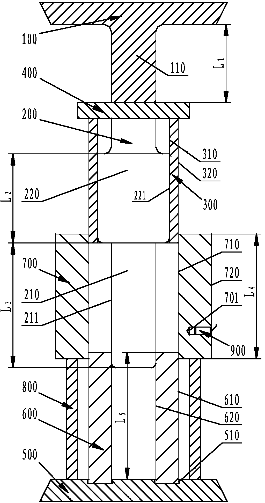
[0087] Firstly, according to the size requirements of the anisotropic ring magnet, the mold of the anisotropic ring magnet of the present invention is designed, and each part of the mold of the anisotropic ring magnet is made of cemented carbide with a brand name of YS2T.

[0088] Then, the forming method of the anisotropic ring magnet is as follows:

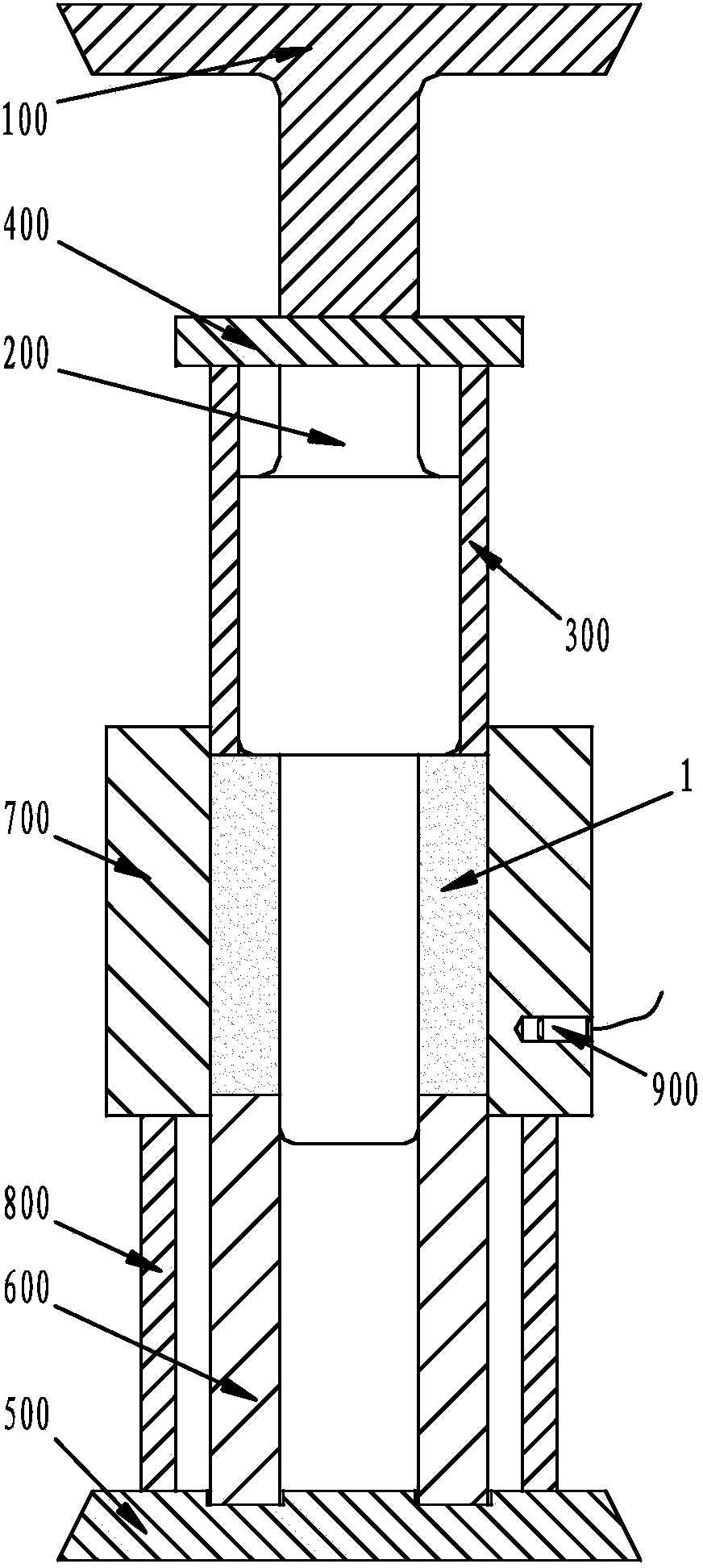
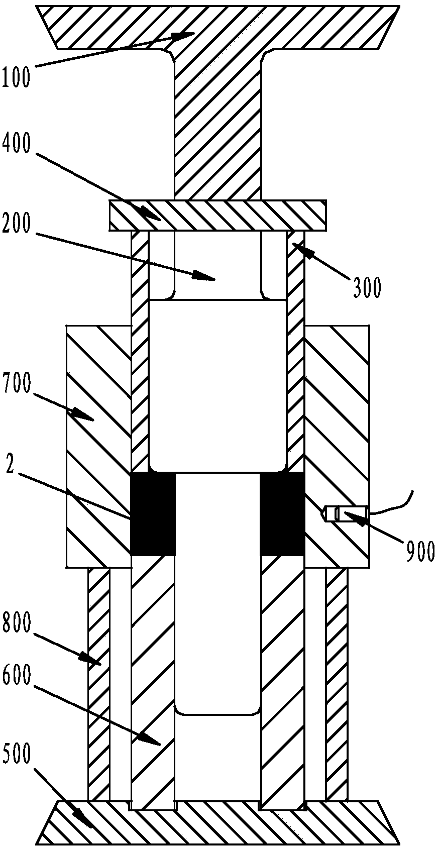
[0089] Step A, the inner wall 710 of the annular die of the mold of the anisotropic ring magnet is provided with a layer of graphite paper with a thickness of 0.38mm, the outer wall and the inner wall of the punch 300 on the ring of the mold, and the inner wall of the mold. The outer wall 211 of the mold core with the upper punch of the mold core is coated with a layer of graphite emulsion;

[0090] Such as figure 2 As shown, weigh 137.5g of rare earth iron-based magnetic powder 1 (u...


PUM


Abstract

The invention provides a die of an anisotropic annular magnet. The die comprises an upper die body and a lower die body; the upper die body comprises an upper annular punch and an upper die core punch arranged inside the upper annular punch, the top of the upper annular punch and the top of the upper die core punch are provided with a base plate, and an upper base is arranged above the base plate; the lower die body comprises a female die supporting ring and a lower annular punch arranged in the female die supporting ring, the female die supporting ring and the lower annular punch are arranged on a lower base, and an annular female die is arranged above the female die supporting ring; the outer wall of the upper annular punch is matched with the inner wall of the annular female die, and the outer wall of a die core of the upper die core punch is matched with the inner wall of the lower annular punch. The invention further provides a forming method of the anisotropic annular magnet. The method comprises the steps that a cavity formed by the upper die core punch, the upper annular punch and the annular female die of the die is filled with magnetic powder, then a hot-pressing technology and a hot deformation technology are conducted in a vacuum or inert gas environment, and the anisotropic annular magnet is processed and formed. By means of the method and the die, the hot-pressing technology and the hot deformation technology are conducted continuously, and production efficiency is high.

Description

technical field [0001] The invention relates to the technical field of manufacturing anisotropic ring magnets, in particular to a molding method of anisotropic ring magnets and a mold thereof. Background technique [0002] Rare-earth iron-based permanent magnet materials have undergone tremendous development since their inception, and have now developed into the third-generation permanent magnet materials represented by NdFeB, which have a series of advantages such as high magnetic performance, wide application, and rapid development. NdFeB permanent magnets mainly include sintered NdFeB magnets, bonded NdFeB magnets and hot-pressed NdFeB magnets. Among them, the rare earth content of bonded NdFeB magnets is low, and its outstanding advantages are high dimensional accuracy, no deformation, no need for secondary processing, and easy mass production; its disadvantages are low magnetic properties due to low rare earth content, and low operating temperature. Sintered NdFeB magn...

Claims


Application Information

Patent Timeline
Patent Type & Authority Applications(China)
IPC IPC(8): B22F3/03B22F5/10B22F3/20H01F41/02
Inventor 张铁桥张澜庭梁乐王静董显平
Owner SHANGHAI JIAO TONG UNIV
Why Eureka
Try Eureka