Abrasive belt grinding and polishing machine

A polishing machine, abrasive belt technology, applied in abrasive belt grinders, grinding/polishing equipment, grinding racks, etc. space saving effect

Active Publication Date: 2014-07-02
WUHU HUIYING AUTOMATIC EQUIP CO LTD
View PDF6 Cites 10 Cited by
  • Summary
  • Abstract
  • Description
  • Claims
  • Application Information

AI Technical Summary

Problems solved by technology

First of all, the connecting bracket is set on the polishing machine. Although it can be rotated relative to the frame driven by the output shaft of the motor, its position on the polishing machine is always the same, that is, no matter whether it needs to use the connecting bracket during work. The grinding wheel and the connecting bracket are all located on the polishing machine inside the abrasive belt, which takes up a lot of space on the polishing machine inside the abrasive belt
In addition, the manipulator used to hold the workpiece during grinding needs to change the angle and position of each axis on it frequently in order to ensure uniform grinding everywhere on the workpiece. It is very easy to touch the connecting bracket when it is placed, which will affect the stability of the workpiece grinding

Method used


Image

  • Abrasive belt grinding and polishing machine
  • Abrasive belt grinding and polishing machine
  • Abrasive belt grinding and polishing machine

Examples


Embodiment 1

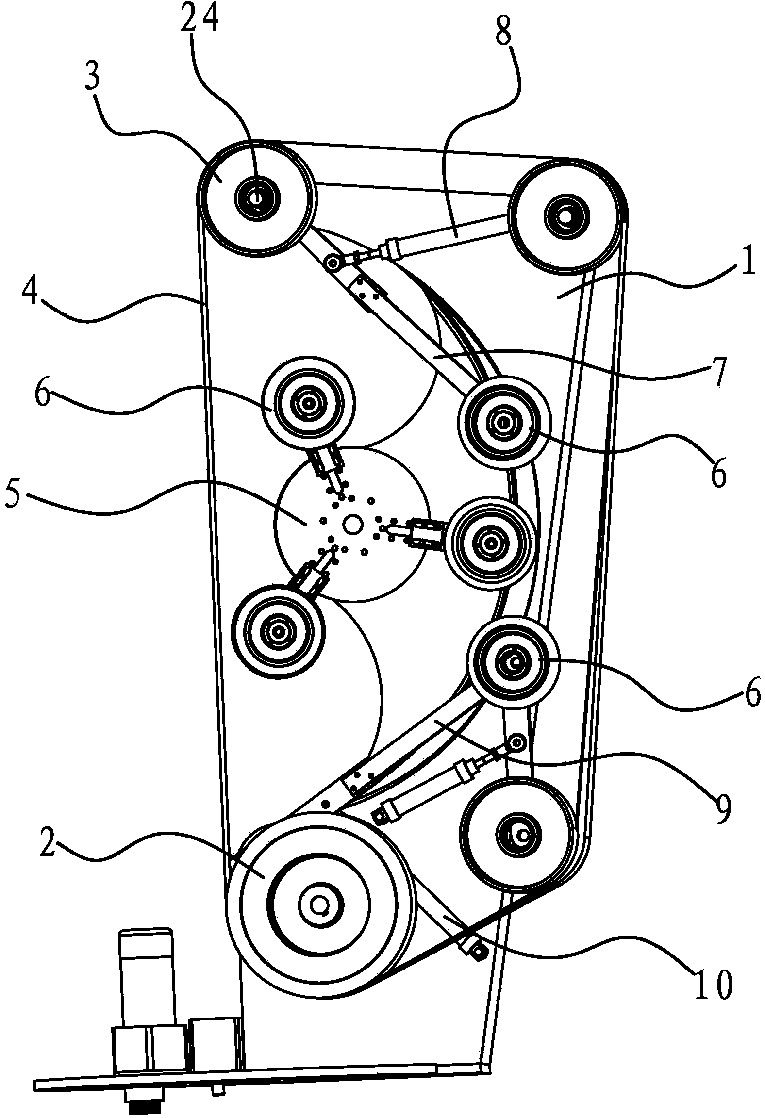
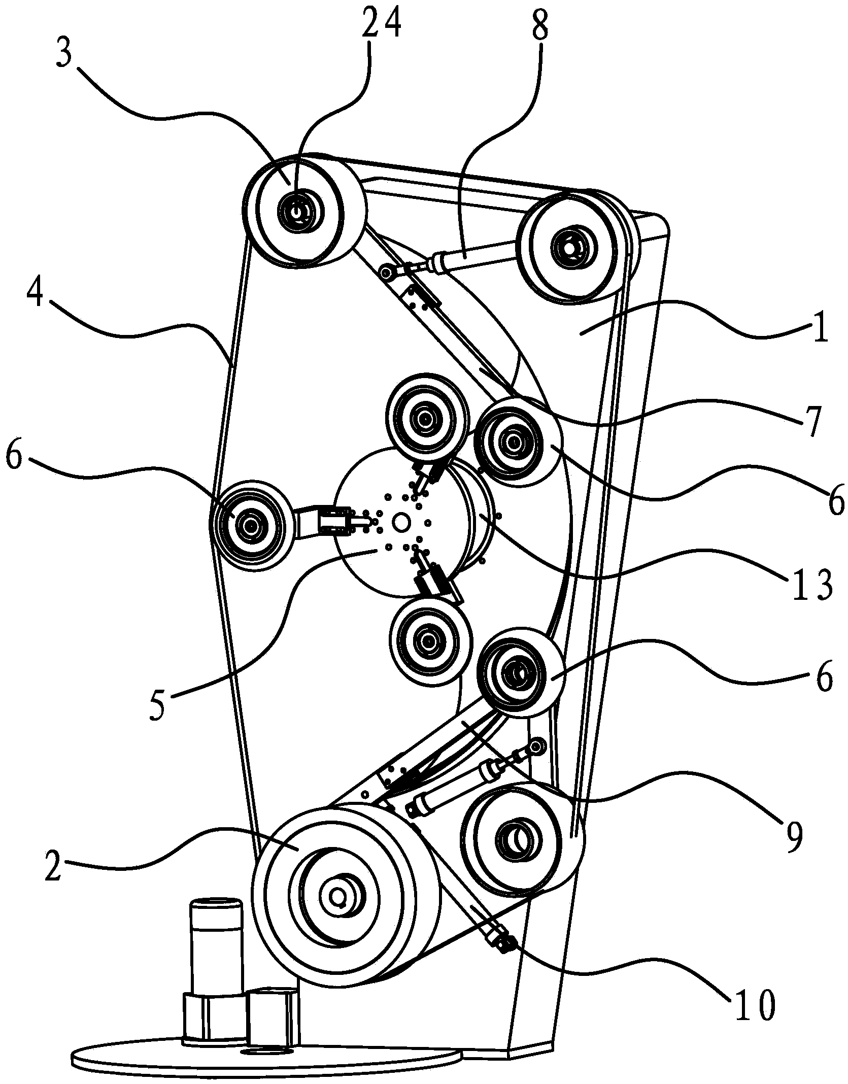
[0044] Such as figure 1 , image 3 and Figure 5 As shown, an abrasive belt grinding and polishing machine includes a frame 1 and a driving wheel 2, a driven wheel 3 and an abrasive belt 4 arranged on the frame 1. A turntable 5 is arranged in the middle of one side of the frame 1, and the periphery of the turntable 5 is A number of grinding wheels 6 are connected with the center of rotation of the rotating disk 5 as the center of the circle, and the curvatures of the wheel edge curved surfaces of each grinding wheel 6 are not the same. The frame 1 is provided with a positioning column 24 near the inner side of the abrasive belt 4 on the upper part of the side of the rotating disk 5. The driven wheel 3 is fixed on the positioning column 24, and a connecting rod 7 is sleeved on the positioning column 24. The connecting rod 7 is Axially fixed between the driven wheel 3 and the side of the frame 1, the end of the connecting rod 7 is fixed with a grinding wheel 6, and the upper p...

Embodiment 2

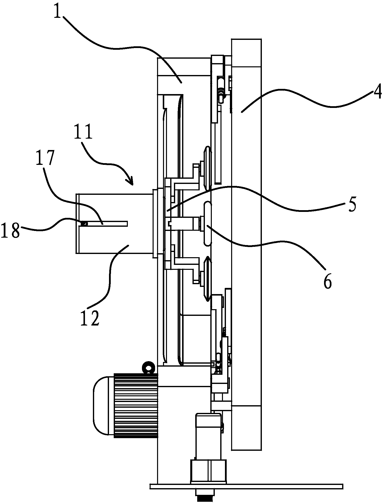
[0058] The structure and principle of this embodiment are basically the same as that of Embodiment 1, the difference is that: the other side of the frame 1 provided with the turntable 5 is fixed with a casing, the driving mechanism includes a rotating motor fixed at the end of the casing, and the frame 1 There is a through hole on the side corresponding to the turntable 5, and the through hole is connected with a positioning sleeve with a cavity inside through a thread, the positioning sleeve is located in the casing and the output shaft of the rotating motor is connected to one end of the positioning sleeve, A rotating motor 14 is arranged in the positioning sleeve, and the output shaft of the rotating motor 14 stretches out from the other end of the positioning sleeve and links to each other with the rotating disk 5 .

[0059] Control the forward rotation of the output shaft of the rotary motor. Since the output shaft of the rotary motor is connected with the positioning slee...

Embodiment 3

[0061] The structure and principle of this embodiment are basically the same as that of Embodiment 1, the difference is that: the other side of the frame 1 provided with the turntable 5 is fixed with a casing, the driving mechanism includes a rotating motor fixed at the end of the casing, and the frame 1 There is a through hole on the side corresponding to the turntable 5, and the through hole is connected with a positioning sleeve with a cavity inside through a screw thread. Inside and at an end of the locating sleeve, an internal gear ring is fixed, a number of transmission gears 2 are also arranged between the transmission gear 1 and the internal gear ring, and a rotating motor 14 is arranged in the positioning sleeve, and the output shaft of the rotating motor 14 is self-positioning. The other end of sleeve protrudes and links to each other with rotating disk 5.

[0062] When the output shaft of the rotary motor rotates forward, the transmission gear 1 at the end of the tr...


PUM


Abstract

The invention provides an abrasive belt grinding and polishing machine, and belongs to the technical field of machines. The abrasive belt grinding and polishing machine solves the problems that the portion, on the inner side of an abrasive belt, of a machine frame of an existing abrasive belt grinding and polishing machine is large in occupied space, and polishing is affected. The abrasive belt grinding and polishing machine comprises a machine frame, a driving wheel, a driven wheel and an abrasive belt, wherein the driving wheel, the driven wheel and the abrasive belt are arranged on the machine frame. A rotary plate is arranged on the machine frame, a plurality of grinding wheels evenly distributed with the rotating center of the rotary plate as the center of the circle are connected to the periphery of the rotary plate, the curvature of the surface of the edges of all the grinding wheels are different, the rotary plate can move in the axis direction of the grinding wheels, a drive mechanism is arranged on the machine frame, and the drive mechanism can drive the rotary plate to move in the axis direction of the grinding wheels to the inner side of the abrasive belt and make the edges of the grinding wheels be right opposite to the inner side of the abrasive belt. The abrasive belt grinding and polishing machine has the advantages that the space, on the inner side of the abrasive belt, of the machine frame is saved, and grinding accuracy and practical value are high.

Description

technical field [0001] The invention belongs to the technical field of machinery and relates to an abrasive belt grinding and polishing machine. Background technique [0002] Abrasive belt grinding and polishing machine is a kind of grinding and polishing machine. It is a common mechanical equipment used for grinding and polishing the surface of workpieces. It is specially used for grinding the surface of metal products such as steel, aluminum and copper, and various non-metallic pipes. Special equipment for polishing. It uses the driving wheel set on the polishing machine to drive the abrasive belt to rotate, and the manipulator used to match it holds the workpiece and contacts the rotating abrasive belt for grinding and polishing. When the traditional abrasive belt grinding and polishing machine is working, the abrasive belt is always flat, so it can only grind and polish the surface of the workpiece on a regular plane. Grinding complex surfaces is time-consuming and lab...

Claims


Application Information

Patent Timeline
Patent Type & Authority Applications(China)
IPC IPC(8): B24B21/16B24B21/18
CPCB24B27/0076B24B27/0092B24B41/02
Inventor 陈启岳
Owner WUHU HUIYING AUTOMATIC EQUIP CO LTD
Why Eureka
Try Eureka