Pressing ring type double-screw spiral oil press

A twin-screw, oil press technology, applied in presses, mechanical equipment, gear transmission devices, etc., can solve the problems of large cumulative error, many deceleration stages, and large volume, so as to reduce production and manufacturing costs and reduce manufacturing difficulty. , The effect of simple operation and maintenance

Inactive Publication Date: 2014-07-02
苟安富 +1
View PDF11 Cites 6 Cited by
  • Summary
  • Abstract
  • Description
  • Claims
  • Application Information

AI Technical Summary

Problems solved by technology

[0003] Moreover, the transmission mode of the single-screw screw oil press adopts the traditional gear structure, which is relatively large in size and has many deceleration stages, so there are many parts and large accumulated errors in manufacturing. It is difficult to ensure smooth transmission, reduce noise and vibration, and manufacture The cost is also higher
[0004] For this reason, a small number of twin-screw screw oil presses appearing in the domestic market are developed on the basis of the original squeeze bar type single-screw screw oil press. Although the problem of cold pressing has been solved, the cage mechanism still uses It is a squeeze bar type press chamber structure. The inner cavity of the press bar type press chamber is integrated by several press bars. The transmission mode still adopts the traditional gear structure. The structure is complex, there are many parts, the equipment manufacturing cost is extremely high, and the operation and maintenance are relatively trouble
Therefore, it is difficult to popularize screw oil presses in the vast rural areas and small and medium-sized oil press enterprises in my country where the number of screw oil presses is the largest.

Method used


Image

  • Pressing ring type double-screw spiral oil press
  • Pressing ring type double-screw spiral oil press
  • Pressing ring type double-screw spiral oil press

Examples


Embodiment Construction

[0025] Specific embodiments of the present invention are described below so that those skilled in the art can understand the present invention, but it should be clear that the present invention is not limited to the scope of specific embodiments, and for those of ordinary skill in the art, as long as various changes Within the spirit and scope of the present invention defined and determined by the appended claims, these changes are obvious, and all inventions and creations using the concept of the present invention are included in the protection list.

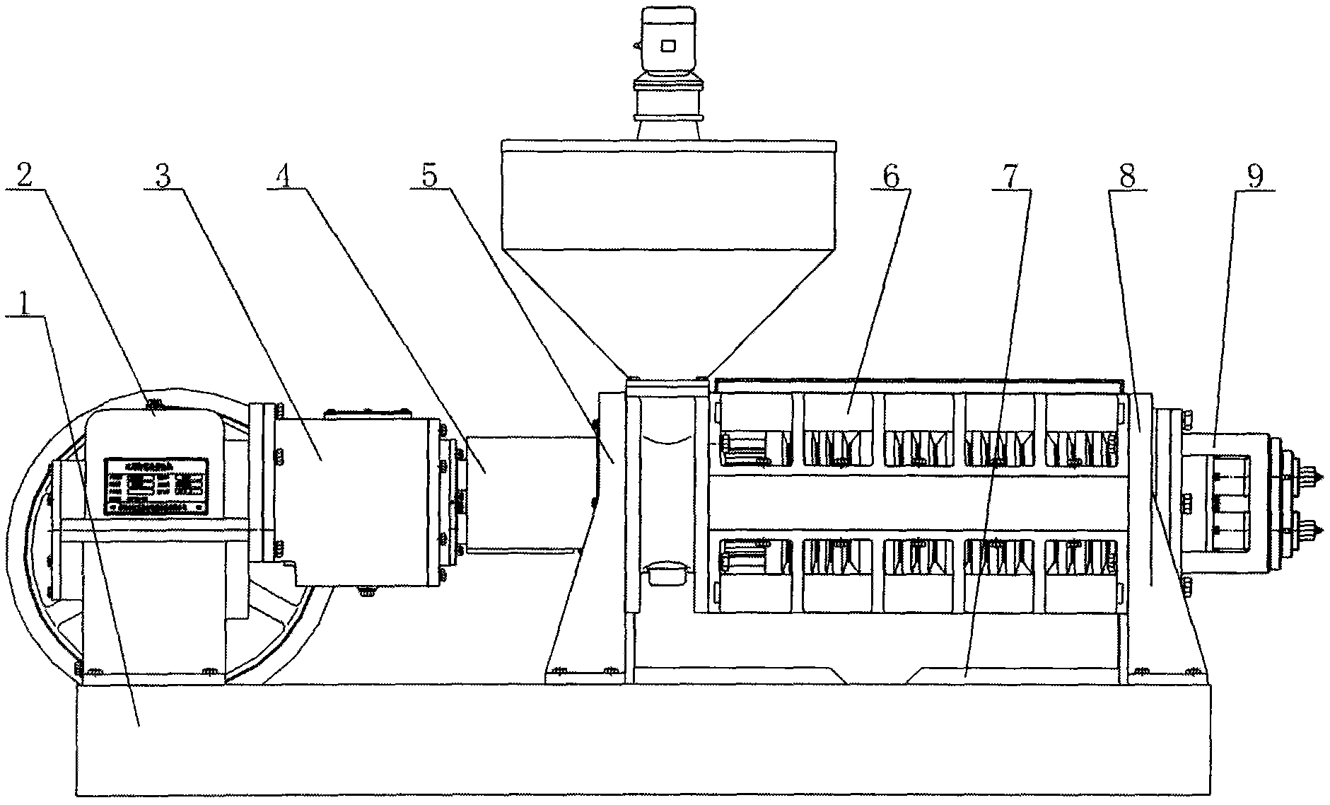
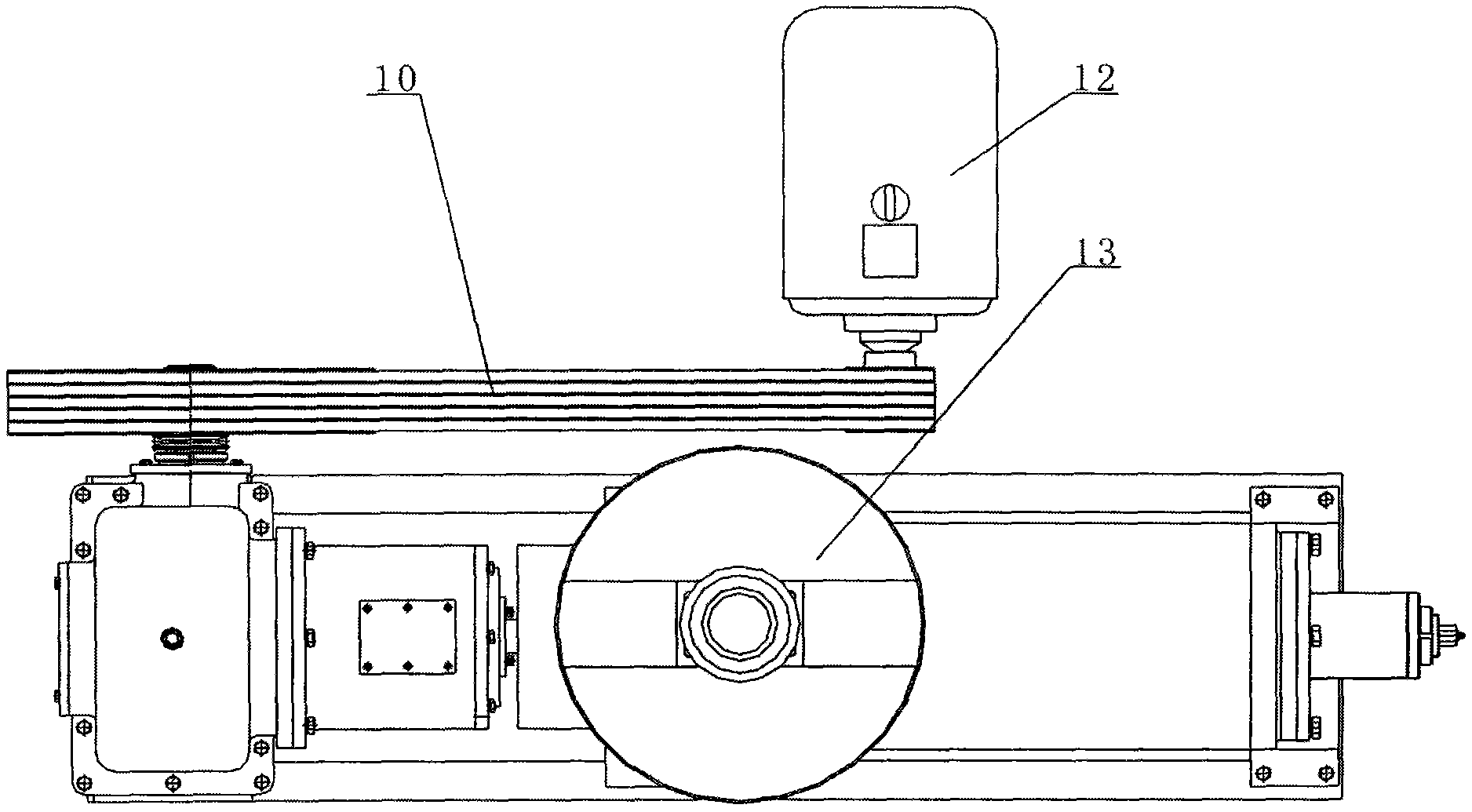
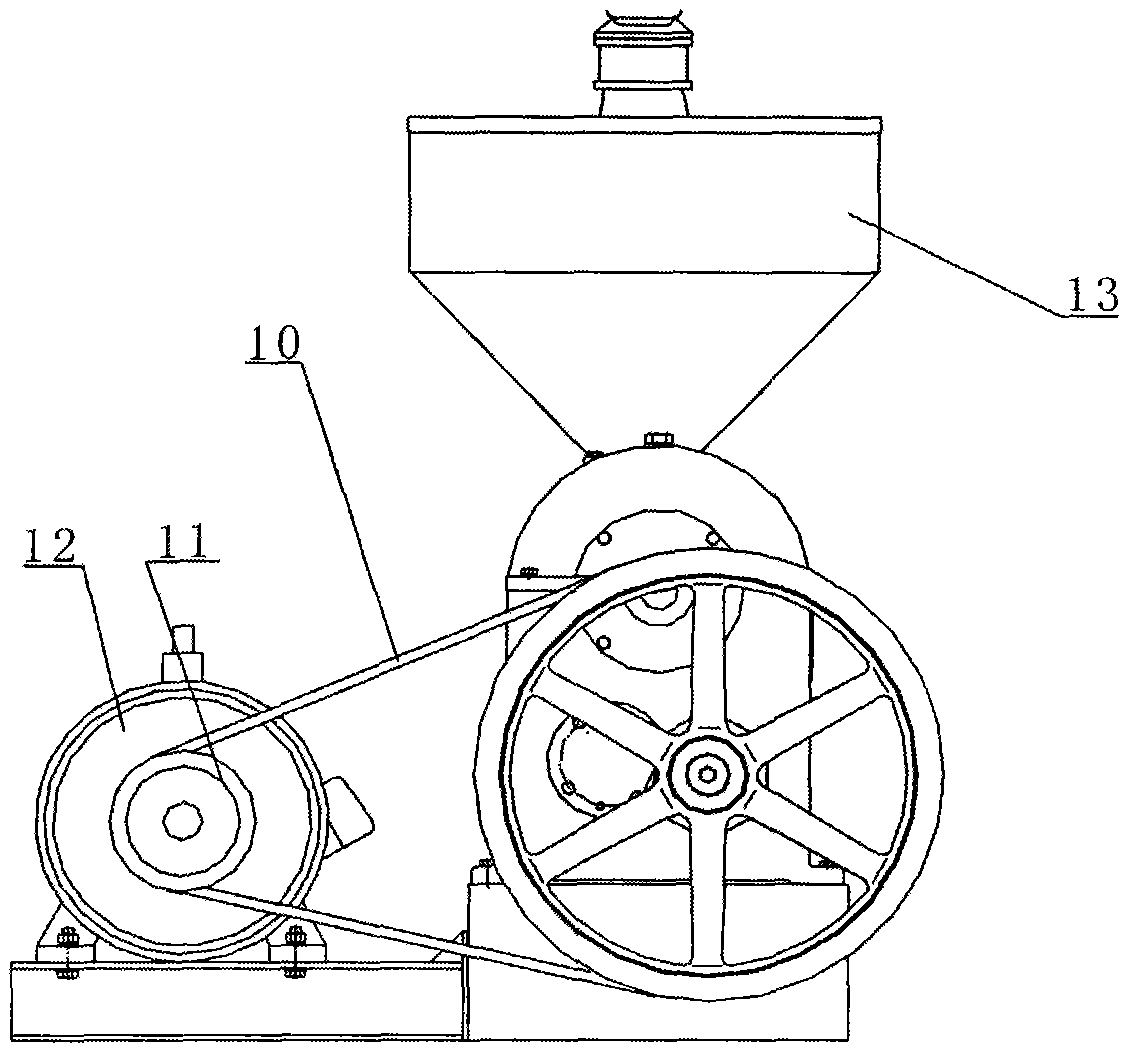
[0026] Such as Figure 1 to Figure 3 As shown, the ring type twin-screw screw oil press includes a machine base 1, a motor 12 installed on the machine base 1, a transmission mechanism 2, a left support frame 5 and a right support frame 8; the motor 12 communicates with the transmission belt 10 The mechanism 2 is connected; wherein, the transmission belt 10 is preferably a V-belt.

[0027] A cage mechanism 6 is installed betwee...


PUM


Abstract

The invention discloses a pressing ring type double-screw spiral oil press comprising a base, a motor mounted on the base, a transmission mechanism, a left support and a right support. The motor is connected to the transmission mechanism through a conveying belt. A pressing cage mechanism is mounted between the left support and the right support, an oil collecting plate is mounted below the pressing cage mechanism, and the tail of the pressing cage mechanism is provided with an oil cake regulating mechanism. A three-way feeding hole communicated with the pressing cage mechanism is formed in the left support, and the left support is provided with a feeding mechanism communicated with the three-way feeding hole. The pressing ring type double-screw spiral oil press is characterized in that the transmission mechanism is connected to a power distribution mechanism which is connected to the pressing cage mechanism; the pressing chamber of the pressing cage mechanism comprises a plurality of pressing rings mounted in a pressing cage; the end face of one side of the pressing ring is provided with a plurality of oil discharging grooves. The pressing ring type double-screw spiral oil press has the advantages that structure is simple, parts are few, equipment manufacturing cost is low, operation and maintenance can be performed simple and conveniently, and cold pressing and hot pressing can be performed both.

Description

technical field [0001] The invention relates to a pressing device for extruding oil-containing plants to extract oil, in particular to a ring-type twin-screw screw oil press. Background technique [0002] Screw oil press is a relatively advanced continuous pressing oil-making machinery and equipment widely used at home and abroad. my country is a big producer of vegetable oil. Vegetable oil is one of the important pillars of the food industry and the main edible oil for our people. Screw oil press It is widely used to extract oil from vegetable oil. The current screw oil press is mainly a single-screw screw oil press, which is suitable for hot pressing. Since the single-screw screw oil press mainly relies on friction to realize the transportation of materials, it needs oil to have a solid matrix similar to thick fibers to produce Friction, so it becomes very sensitive to the temperature, moisture and texture of the pressed oil, and slight fluctuations will have a greater imp...

Claims


Application Information

Patent Timeline
Patent Type & Authority Applications(China)
IPC IPC(8): B30B9/16B30B15/00F16H1/14
CPCB30B9/26
Inventor 冯异苟安富
Owner 苟安富
Why Eureka
Try Eureka