Vertical furnace carbonization chamber with internal gas collection cavities

A carbonization chamber and gas collection chamber technology, applied in the field of continuous vertical furnaces for low-rank coal drying, can solve the problems of poor air permeability of the material layer and difficult separation and treatment, so as to reduce the pressure in the furnace, improve the gas recovery rate, The effect of prolonging the life of the furnace body

Active Publication Date: 2014-07-02
ACRE COKING & REFRACTORY ENG CONSULTING CORP DALIAN MCC
View PDF3 Cites 2 Cited by
  • Summary
  • Abstract
  • Description
  • Claims
  • Application Information

AI Technical Summary

Problems solved by technology

In the prior art, whether it is a West German Coopers furnace type, a continuous vertical furnace type, or other existing furnace types, in order to make the coal in the carbonization chamber have a certain degree of air permeability, it can only be used in production. 13mm lump coal is used as raw material, and pulverized coal with a diameter of less than 6mm cannot be processed due to the poor gas permeability of the material layer
In addition, when the coal gas produced in the low-temperature dry distillation process of low-rank coal passes through the material layer, the coal powder in the coal material is brought into the raw coal gas, so that the subsequent coal tar contains a large amount of coal powder, which is difficult to separate and process

Method used


Image

  • Vertical furnace carbonization chamber with internal gas collection cavities
  • Vertical furnace carbonization chamber with internal gas collection cavities
  • Vertical furnace carbonization chamber with internal gas collection cavities

Examples


Embodiment 1

[0025] [Embodiment 1] A kind of specific application structural form of the present invention

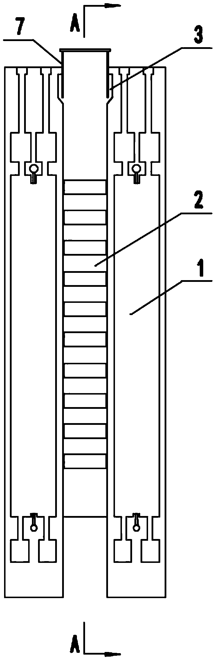
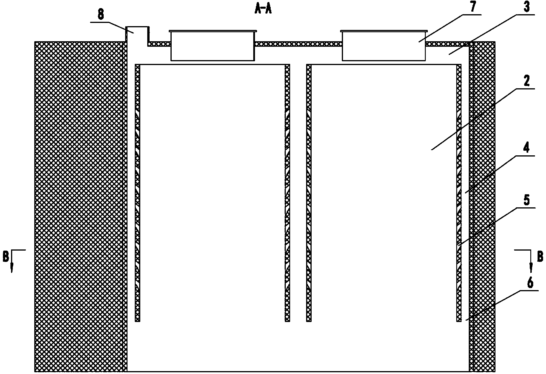
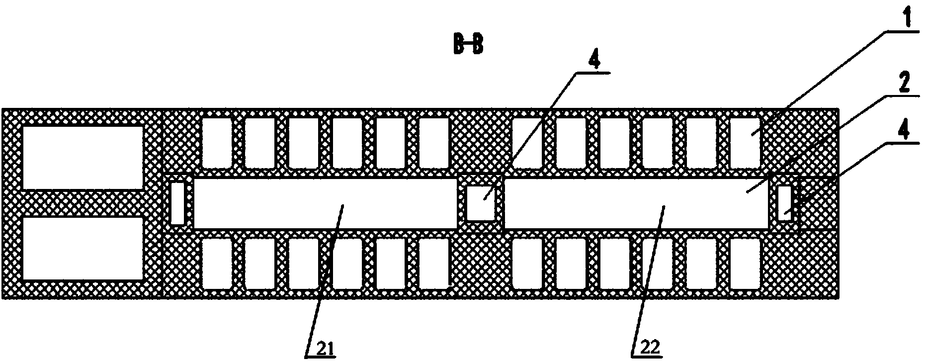
[0026] See Figure 1-Figure 3 , is a structural schematic diagram of an embodiment of a vertical furnace carbonization chamber with an inner gas collection chamber according to the present invention, including a combustion chamber 1 21 and a carbonization chamber 2 22, and gas collection chambers are arranged at both ends and / or in the middle of each door carbonization chamber 2 There is a gas outlet hole 5 between the carbonization chamber 2 and the gas collection chamber 4, and the gas outlet hole 5 is set at an interval of 0.5 to 1 meter along the height. 5 is not blocked by the descending coal material, and is conducive to the export of raw gas, and can also prevent the coal material in the carbonization chamber 2 from entering the gas collection chamber 4 through the gas outlet hole 5 . The height of gas outlet hole 5 is 40~100mm.

[0027] The bottom 6 of the gas-collecting c...


PUM


Abstract

The invention relates to a vertical furnace carbonization chamber with internal gas collection cavities. The vertical furnace carbonization chamber comprises a carbonization chamber, wherein gas collection cavities are arranged at the two ends and / or in the middle of the carbonization chamber along the height direction of the carbonization chamber; coal gas export holes are formed between the carbonization chamber and the gas collection cavities; a convergence gas channel is arranged at the top of the carbonization chamber, is communicated with each gas collection cavity and leads to an ascending pipe; the gas collection cavities, the coal gas export holes and the convergence gas channel can be formed by refractory bricks and can be also formed by welding heat-resisting steel plates. Compared with the prior art, the vertical furnace carbonization chamber has the beneficial effects that 1) the vertical furnace carbonization chamber can be widely used for preparing tar, coal gases and semi-coke through dry distillation of various low-rank coal, is not limited by feed coal granularity requirements, is suitable for lump coal raw materials and is also suitable for pulverized coal raw materials; 2) the pressure in the furnace can be reduced, furnace body blowby can be reduced, the coal gas recovery rate can be increased, the production safety can be improved, and the furnace body life can be prolonged; 3) the amount of coke powder entrained by raw gas produced by the device is smaller, and coal tar and coal gases with higher quality can be produced.

Description

technical field [0001] The invention relates to the technical field of continuous vertical furnaces for low-rank coal drying, in particular to a carbonization chamber of a vertical furnace with an inner gas collection chamber. Background technique [0002] In the 1970s and 1980s, vertical furnaces were widely used to produce city gas and semi-coke. In recent years, with the development of low-rank coal utilization technology, vertical furnaces are often used for medium-low temperature dry distillation of low-rank coal to produce semi-coke and gas, and extract coal tar from them. In the prior art, whether it is a West German Coopers furnace type, a continuous vertical furnace type, or other existing furnace types, in order to make the coal in the carbonization chamber have a certain degree of air permeability, it can only be used in production. 13mm lump coal is used as a raw material, and pulverized coal with a diameter of less than 6mm cannot be processed due to the poor a...

Claims


Application Information

Patent Timeline
IPC IPC(8): C10B1/04C10B53/04
Inventor 李有军刘洪春刘承智
Owner ACRE COKING & REFRACTORY ENG CONSULTING CORP DALIAN MCC
Why Eureka
Try Eureka