Flue gas desulfurization and denitration system

A technology for desulfurization, denitrification and flue gas, applied in the field of flue gas desulfurization and denitrification systems, can solve the problems of unstable system operation, high power consumption of booster fans, acid condensation and corrosion, etc., to improve operation stability and safety, increase The effect of regeneration and desorption time and the prevention of acid condensation corrosion

Pending Publication Date: 2019-01-11
LIANFENG STEEL (ZHANGJIAGANG) CO LTD
View PDF0 Cites 12 Cited by
  • Summary
  • Abstract
  • Description
  • Claims
  • Application Information

AI Technical Summary

Problems solved by technology

[0005] (1) When the concentration of particulate matter in the flue gas exceeds 100mg / m3, it is easy to cause the resistance of the adsorption tower to increase in a short period of time. When the tower resistance of the adsorption tower is greater than 3KPa, the workshop will be forced to reduce production;
[0006] (2) After the high-temperature flue gas of about 160°C from the sintering machine enters the cold air, the temperature can only be reduced to 120°C~130°C. In the process of entering the adsorption tower, the power consumption of the booster fan is high, and the heat energy of the flue gas cannot be effectively utilized;
[0007] (3) When the low-temperature cooling fan passes the cold air into the cooling section of the regeneration tower, the heat exchange tubes in the cooling section of the regeneration tower are easily washed by the cold air and corroded by acid condensation. After the heat exchange tube leaks due to corrosion, it is very easy to cause the active coke in the heat exchange tube in the cooling section of the regeneration tower to spontaneously ignite, resulting in a serious "fire accident" inside the regeneration tower; and the heat exchange tube in the cooling section of the regeneration tower is due to Corrosion leakage will also lead to high furnace pressure, which is not conducive to the safe operation of the furnace;
[0008] (4) During the screening of active coke by the vibrating screen, the fine powder and part of the ash diffused in the upper chamber of the vibrating screen will enter the adsorption tower together with the large-particle activated coke, resulting in the emission of flue gas from the chimney. The content of flue gas particles in the air is high, and the average value of the emitted flue gas particles is greater than 20 mg / m3, which is difficult to meet future environmental protection requirements;
[0009] (5) The system is unstable, and the desulfurization and denitrification efficiency is lower than 60%

Method used


Image

  • Flue gas desulfurization and denitration system
  • Flue gas desulfurization and denitration system

Examples


Embodiment Construction

[0026] The present invention will be further described below in conjunction with the accompanying drawings and specific embodiments.

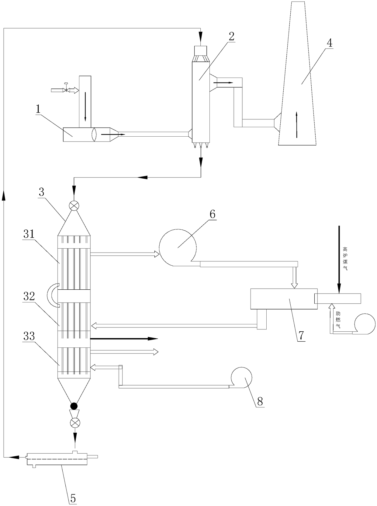
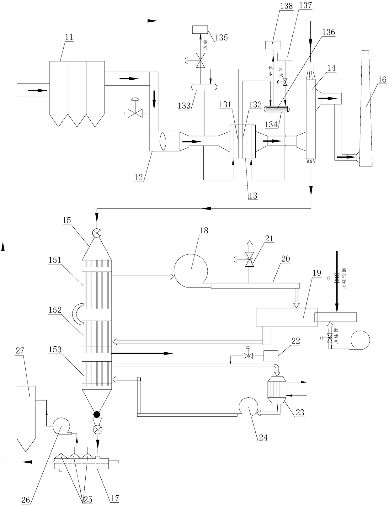
[0027] like figure 1 As shown, the flue gas desulfurization and denitrification system includes a bag filter 11, a booster fan 12, a waste heat boiler 13, an adsorption tower 14 and a regeneration tower 15, and the outlet of the bag filter 11 passes through a booster fan 12 It is connected with the smoke inlet of the waste heat boiler 13, the smoke outlet of the waste heat boiler 13 is connected with the smoke inlet of the adsorption tower 14, the smoke outlet of the adsorption tower 14 is connected with the chimney 16, and the outlet at the bottom of the adsorption tower 14 is The feed port is connected with the feed port at the top of the regeneration tower 15, the discharge port at the bottom of the regeneration tower 15 is connected with the feed port of the vibrating screen 17, and the oversize discharge port of the vibrating screen 17 is ...


PUM


Abstract

The invention discloses a flue gas desulfurization and denitration system. The system comprises a bag deduster, a booster fan, a waste heat boiler, an adsorption tower and a regeneration tower, the outlet of the bag deduster is communicated with the flue gas inlet of the waste heat boiler through the booster fan, the flue gas outlet of the waste heat boiler is communicated with the flue gas inletof the adsorption tower, the flue gas outlet of the adsorption tower is communicated with the chimney, a material outlet at the bottom of the adsorption tower is communicated with a material inlet atthe top of the regeneration tower, a material outlet at the bottom of the regeneration tower is communicated with a material inlet of a vibrating screen, and the oversize product outlet of the vibrating screen is communicated with a material inlet at the top of the adsorption tower. The system has the advantages of high long-term running stability, high safety, high desulfurization and denitrationefficiency, and realization of safe and ultralow emission of the flue gas.

Description

technical field [0001] The invention relates to the technical field of flue gas treatment in metallurgy, coal power, nonferrous metals, and cement industries, in particular to a flue gas desulfurization and denitrification system using activated coke for flue gas desulfurization and denitrification. Background technique [0002] In the metallurgy, coal power, non-ferrous metal and cement industries, the high-temperature flue gas from the sintering machine needs to be desulfurized and denitrified by the flue gas desulfurization and denitrification system before being discharged from the chimney. like figure 1 As shown, the structure of the currently used flue gas desulfurization and denitrification system includes: a booster fan 1, an adsorption tower 2 and a regeneration tower 3, the outlet of the booster fan 1 is connected to the smoke inlet of the adsorption tower 2, and the adsorption tower The smoke outlet of 2 is connected with the chimney 4, the discharge port at the ...

Claims


Application Information

Patent Timeline
Patent Type & Authority Applications(China)
IPC IPC(8): B01D53/02B01D46/02F22B1/18F27D17/00
CPCB01D46/02B01D53/02B01D2253/102B01D2257/302B01D2257/404B01D2258/0283B01D2259/40088F22B1/1807F27D17/00F27D17/004Y02E20/30Y02P10/25
Inventor 赵海亮田园欧叡刘静张彬
Owner LIANFENG STEEL (ZHANGJIAGANG) CO LTD
Why Eureka
Try Eureka