Circulating fluidized bed garbage incineration boiler and pollution control system with same

A circulating fluidized bed and waste incineration technology, applied in incinerators, combustion methods, combustion types, etc., can solve the economic problems affecting waste incineration plants, slag discharge difficulties, pollution and other problems

Active Publication Date: 2012-07-04
无锡光核新能源建设有限公司
View PDF11 Cites 27 Cited by
  • Summary
  • Abstract
  • Description
  • Claims
  • Application Information

AI Technical Summary

Problems solved by technology

[0012] The purpose of the present invention is to solve the difficulty of slagging in the existing circulating fluidized bed garbage incinerator, which needs to stop the furnace regularly to remove the slag, clean up the lar

Method used


Image

  • Circulating fluidized bed garbage incineration boiler and pollution control system with same
  • Circulating fluidized bed garbage incineration boiler and pollution control system with same
  • Circulating fluidized bed garbage incineration boiler and pollution control system with same

Examples


specific Embodiment approach 1

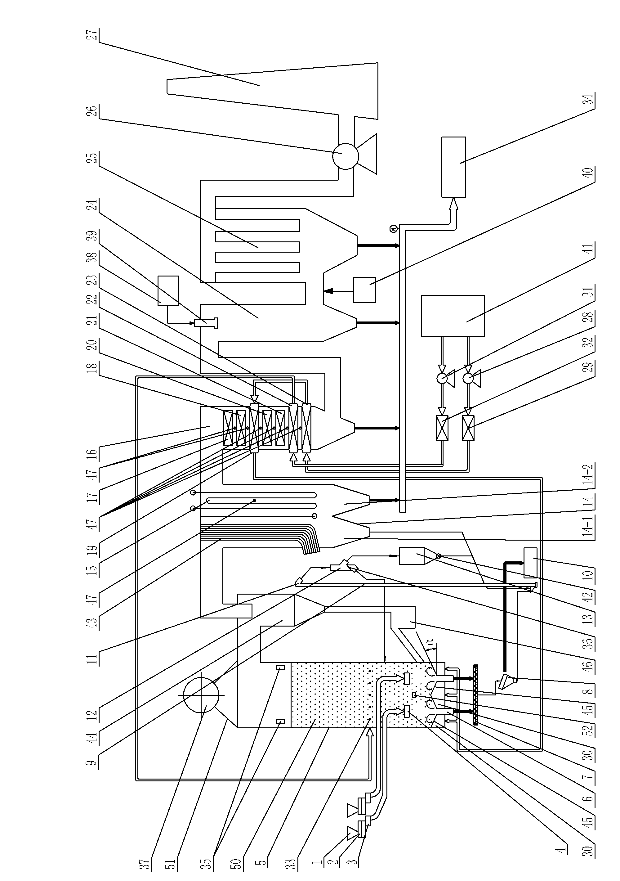
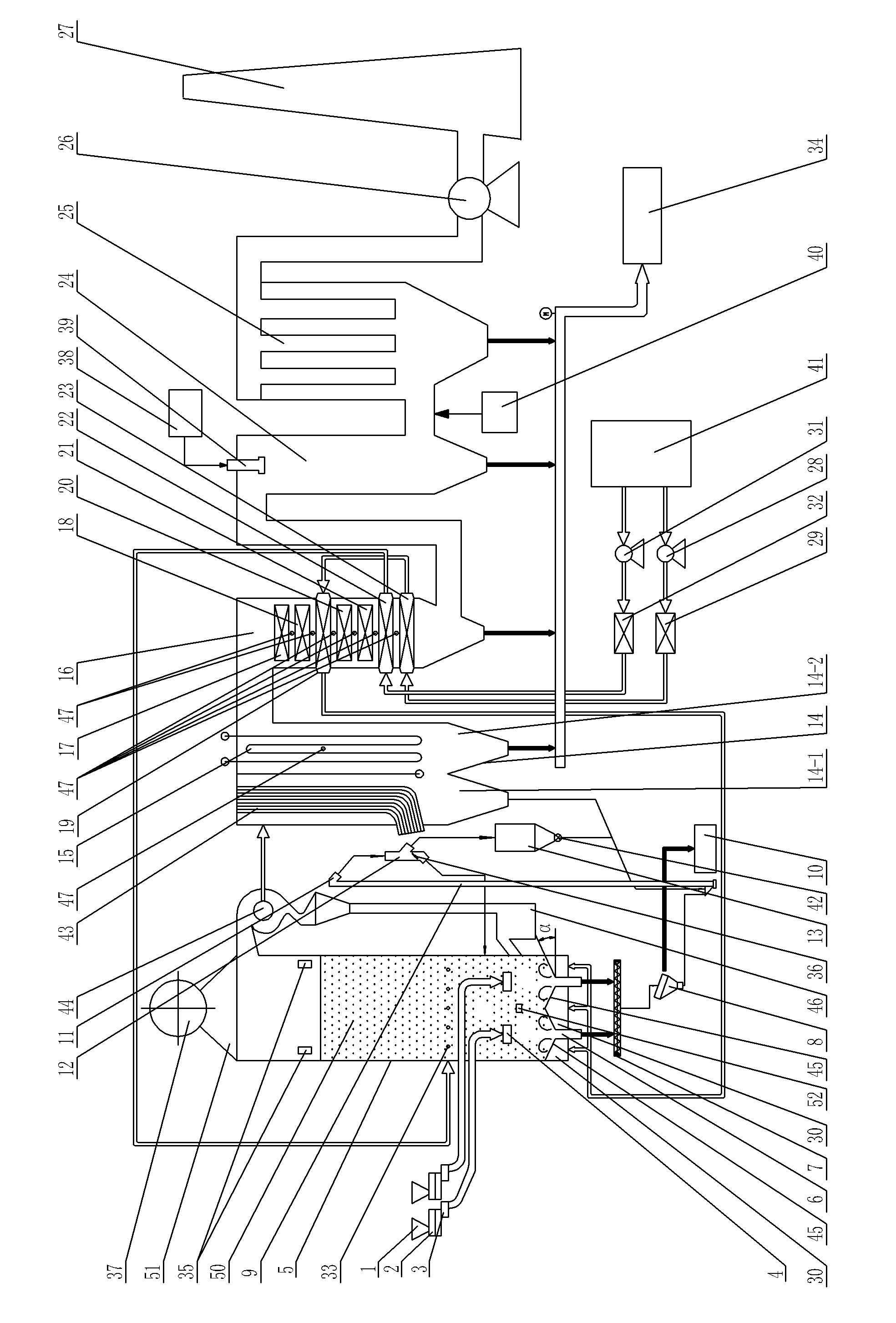
[0028] Specific implementation mode one: combine figure 1 and figure 2 Explain that the circulating fluidized bed waste incineration boiler of this embodiment includes a waste feeding port 4, a furnace body 5, a slag discharge port 6, a water-cooled double-helix auger 7, a vibrating screen 8, a lifting bucket 9, a non-combustible Material storage bin 10, distribution valve 12, bed material storage bin 13, flue gas cooling chamber 14, high temperature superheater 15, tail flue 16, upper low temperature superheater 17, lower low temperature superheater 18, primary air upper air preheater 19. Upper economizer 20, lower economizer 21, secondary air air preheater 22, primary air lower air preheater 23, primary fan 28, primary air steam air preheater 29, air chamber 30, secondary Secondary fan 31, secondary air steam air preheater 32, secondary air inlet 33, rotary valve 36, steam drum 37, star discharge valve 42, water cooling screen 43, separator 44, air distribution plate 45, U...

specific Embodiment approach 2

[0036] Specific implementation mode two: combination figure 1 and figure 2 Explain that the pollution control system of the circulating fluidized bed waste incineration boiler described in the first embodiment is installed in this embodiment, and the system includes a circulating fluidized bed waste incineration boiler 51; the system also includes a semi-dry reaction tower 24 , bag filter 25, induced draft fan 26, chimney 27, fly ash bin 34, lime slurry preparation system 38, rotary sprayer 39 and activated carbon injection device 40;

[0037] The lower rear side wall of the tail flue 16 of the circulating fluidized bed waste incineration boiler 51 communicates with the flue gas inlet of the semi-dry reaction tower 24 through the flue. The top of the semi-dry reaction tower 24 is provided with a rotary sprayer 39, which The sprayer 39 communicates with the lime slurry preparation system 38 through pipelines, the semi-dry reaction tower 24 communicates with the bag filter 25 ...

specific Embodiment approach 3

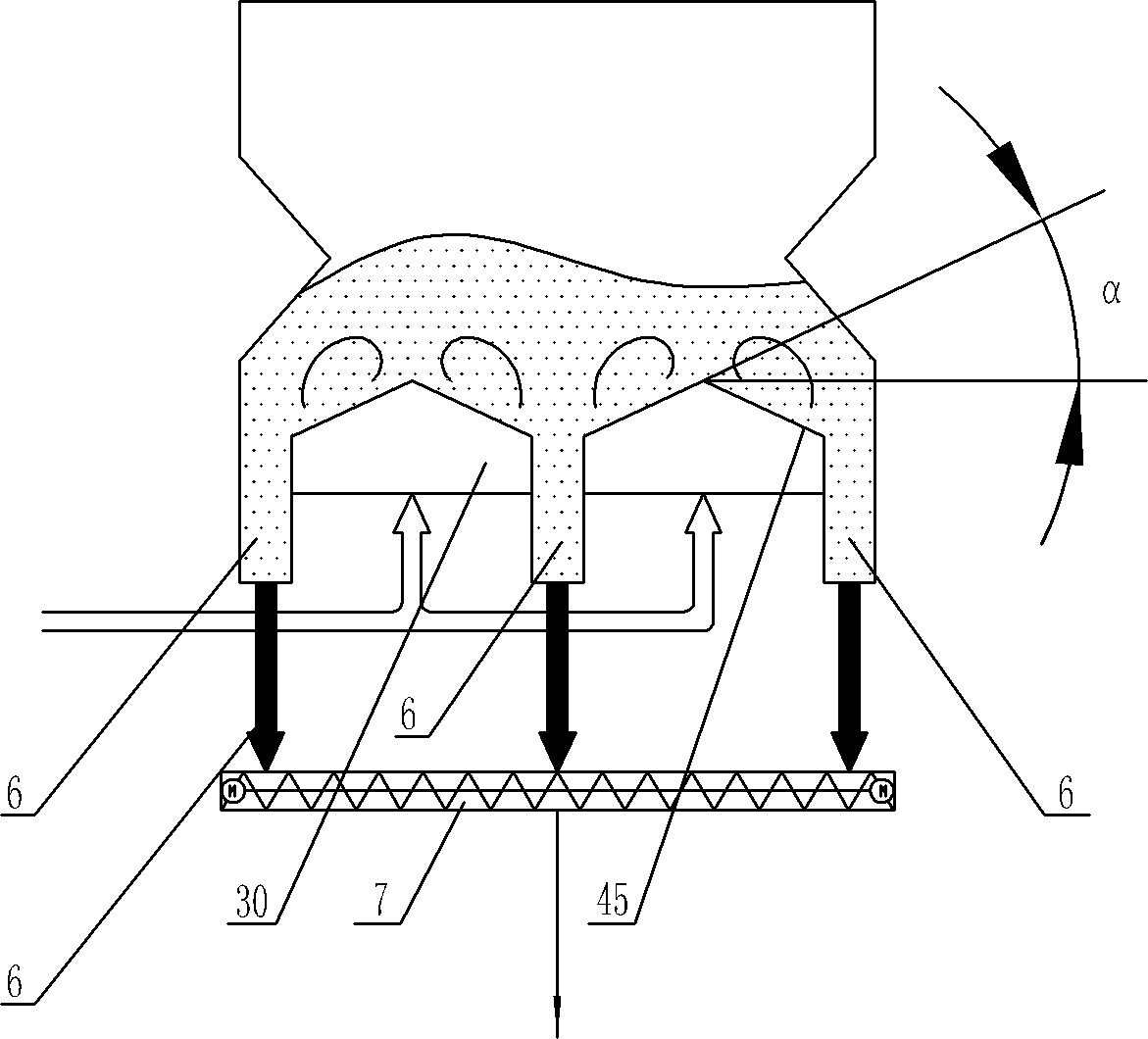
[0038] Specific implementation mode three: combination Figure 1 ~ Figure 3 Note, in this embodiment, the figure 1 and figure 2 The double "V" shaped air distribution panels in the image 3 The double inverted "V" shaped air distribution board in the middle is enough;

[0039] The circulating fluidized bed garbage incineration boiler of this embodiment, the boiler includes a garbage feeding port 4, a furnace body 5, a slag discharge port 6, a water-cooled double-helix auger 7, a vibrating screen 8, a lifting bucket 9, a non-combustible storage Bin 10, distribution valve 12, bed material storage bin 13, flue gas cooling chamber 14, high temperature superheater 15, tail flue 16, upper low temperature superheater 17, lower low temperature superheater 18, primary air upper air preheater 19, Upper economizer 20, lower economizer 21, secondary air air preheater 22, primary air lower air preheater 23, primary fan 28, primary air steam air preheater 29, air chamber 30, secondary f...


PUM


Abstract

The invention discloses a circulating fluidized bed garbage incineration boiler and a pollution control system with the same, which relate to a garbage incineration boiler and a pollution control system with the same, and aim to solve the problems that the conventional circulating fluidized bed garbage incineration furnace difficultly discharges slag and is required to be stopped regularly to remove the slag and the economy of a garbage incineration plant is influenced. According to the scheme I, a circulating fluidized bed and double V-shaped wind distributing plates are arranged in a boiler body, the boiler body, a separator, a flue gas cooling chamber and a tail flue are communicated in sequence, an upper level low-temperature superheater, a lower level low-temperature superheater, a primary wind air preheater, a secondary wind air preheater, an upper level primary wind economizer, a lower level primary wind economizer, an upper level secondary wind economizer and a lower level secondary wind economizer are arranged in the tail flue, and the separator is communicated with the boiler body by a U-shaped valve; different from the scheme I, the scheme III is characterized in that: double inverted V-shaped wind distributing plates are adopted; different from the scheme III, the scheme V is characterized in that: an inverted V-shaped wind distributing plate is adopted; and according to the scheme II, the scheme IV and the scheme VI, a semidry reaction tower, a bag-type dust collector, an induced draft fan, a chimney, a fly ash cabin, a lime slurry preparation system, a rotary atomizer and an active carbon injecting device are added on the basis of the scheme I, the scheme III and the scheme V. The circulating fluidized bed garbage incineration boiler and the pollution control system with the same are used for incinerating garbage, and pollutant emission can be controlled.

Description

technical field [0001] The invention relates to a garbage incineration boiler and a pollutant control system thereof. Background technique [0002] According to statistics, in 2011, the total output of domestic waste in my country has exceeded 290 million tons, and it is increasing at an annual rate of 8% to 10%. A huge amount of urban garbage has become a problem that plagues my country's economic development. The incineration method has the advantages of saving land, eliminating various pathogens, large processing capacity, and fast speed. It is also equipped with a heat recovery power generation system and a waste incineration tail gas treatment system. The social and environmental benefits are huge, so the proportion of waste incineration is gradually increasing. [0003] The types of waste incineration boilers mainly include mechanical grate incinerators, rotary kiln incinerators and fluidized bed or circulating fluidized bed incinerators. Due to the lack of classific...

Claims


Application Information

Patent Timeline
IPC IPC(8): F23G5/30F23G5/44F23J15/00
Inventor 别如山宋兴飞纪晓瑜黄兵朱少飞刘茜茜陈佩
Owner 无锡光核新能源建设有限公司
Why Eureka
Try Eureka