Improved pneumatic vectoring nozzle structure with function of injecting double secondary flow branches

A technology of vector nozzle and secondary flow, applied in the direction of machine/engine, jet propulsion device, etc., can solve the problems of reduced engine flow and reduced thrust

Inactive Publication Date: 2014-07-02
NORTHWESTERN POLYTECHNICAL UNIV
View PDF7 Cites 13 Cited by
  • Summary
  • Abstract
  • Description
  • Claims
  • Application Information

AI Technical Summary

Problems solved by technology

[0003] In order to overcome the deficiencies in the background technology, in order to solve the defect that the bleed air from the high-pressure parts of the engine reduces the engine flow and causes the thrust to drop, the present invention provides an aerodynamic vectoring nozzle structure with two secondary flow injections

Method used


Image

  • Improved pneumatic vectoring nozzle structure with function of injecting double secondary flow branches

Examples


Embodiment Construction

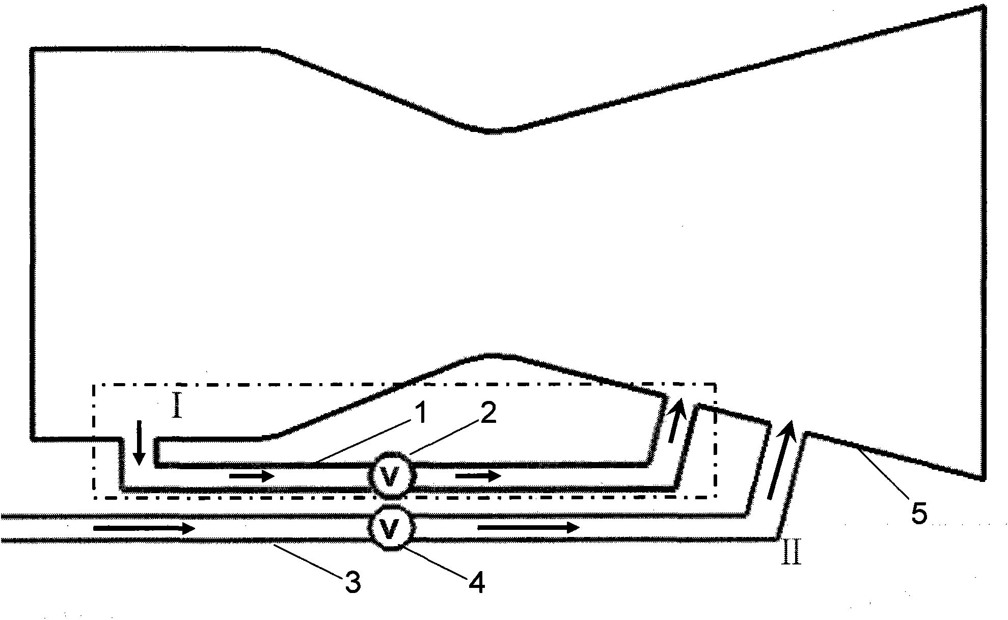
[0009] With reference to each figure, this a kind of aerodynamic vectoring nozzle structure with two secondary flow injections is characterized in that its structure comprises: the pneumatic vectoring nozzle of two secondary flow injections consists of secondary flow injection system 1, secondary The flow injection system II and the expansion nozzle 5 are composed; the secondary flow injection system I includes the bleed air pipeline 1 and the valve 2; the secondary flow injection system II includes the bleed air pipeline 3 and the valve 4;

[0010] The secondary flow injection system I bleeds air from the front end of the nozzle 5 convergence section; the secondary flow injection system II bleeds air from the high-pressure compressor of the engine; the secondary flow injection system I and the secondary flow injection system II are located on the same plane, and the secondary The flow injection system II is positioned at the bottom of the secondary flow injection system I, and...


PUM


Abstract

The invention provides a pneumatic vectoring nozzle structure with a function of injecting double secondary flow branches. The pneumatic vectoring nozzle structure is characterized in that a pneumatic vectoring nozzle with the function of injecting the double secondary flow branches structurally comprises a secondary flow injection system I, a secondary flow injection system II and a closing and converging nozzle; the secondary flow injection system I comprises an air entrainment pipeline and a valve; the secondary flow injection system II comprises another air entrainment pipeline and another valve. The pneumatic vectoring nozzle structure has the advantage that shortcomings of decrease of flow of an engine and reduction of thrust due to the fact that air is entrained from a high-pressure component of the engine can be overcome.

Description

Technical field: [0001] The invention relates to the technical field of aero-engines, in particular to a novel exhaust system structure applied to aero-engines, in particular to an improved aerodynamic vectoring nozzle structure with two secondary flow jets. Background technique: [0002] The application of thrust vectoring technology can greatly improve the flexibility, maneuverability, combat effectiveness and survivability of rockets, missiles and fighter jets. The basis of this technology is thrust vectoring nozzle technology. Since the 1990s, the shock vector control SVC (Shock Vectoring Controlling) method has been used in the research of the aerodynamic thrust vectoring nozzle technology of the exhaust system of the aero-engine. The flow interferes with the mainstream to form a shock wave to generate a thrust vector, and the applicable objects include binary and axisymmetric diverging nozzles. In 1987, Abeyounis et al. of NASA Langley Research Center in the United St...

Claims


Application Information

Patent Timeline
Patent Type & Authority Applications(China)
IPC IPC(8): F02K1/00
Inventor 史经纬王占学孙啸林张明阳章叶川周莉
Owner NORTHWESTERN POLYTECHNICAL UNIV
Why Eureka
Try Eureka