
A spiral multi-channel pulse detonation engine

A pulse detonation and helical technology, used in machines/engines, rocket engine devices, mechanical equipment, etc., can solve the problems of wasting engine space utilization, increasing filling difficulty, and difficulty in increasing detonation frequency.

Inactive Publication Date: 2016-01-13
NORTHWESTERN POLYTECHNICAL UNIV
View PDF4 Cites 0 Cited by
  • Summary
  • Abstract
  • Description
  • Claims
  • Application Information

AI Technical Summary

Problems solved by technology

However, both have obvious deficiencies. The internal flow resistance of the spiral pipe is greater than that of the straight pipe with the same pipe diameter. The filling of the head increases the difficulty of filling and it is difficult to increase the detonation frequency.
If the fuel is liquid fuel, when the head of the spiral tube is filled, the probability of the oil-gas mixture hitting the wall after atomization is much higher than that of the straight tube, and it is easy to form droplets, which increases the difficulty of atomization
The guiding line of the helical tube is a helical line, and the helical tube is formed by stretching a circular ring along the guiding line. The circular surface is always perpendicular to the guiding line, its radius is much larger than that of the detonation tube, and the windward area along the axial direction is much larger than that of the same tube. The frontal area of ​​the straight tube with the diameter is smaller than that of the straight tube, which is distributed by a single spiral tube, which wastes the space utilization of the engine

Method used

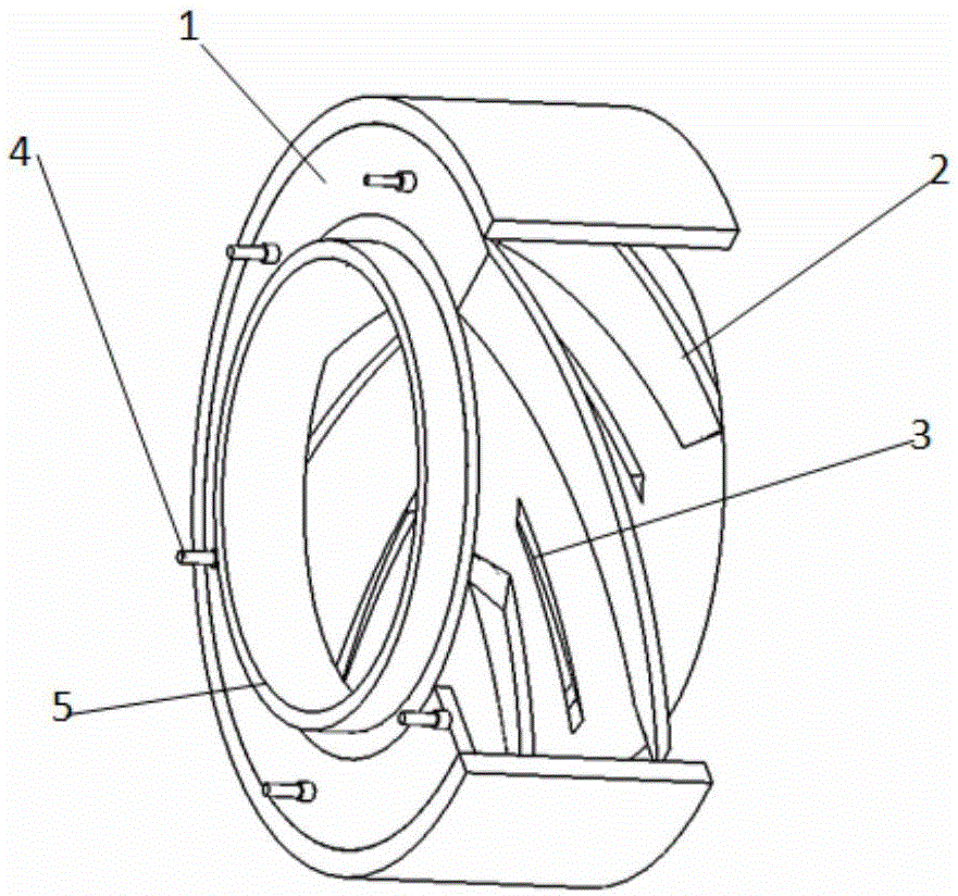

Image

  • A spiral multi-channel pulse detonation engine
  • A spiral multi-channel pulse detonation engine
  • A spiral multi-channel pulse detonation engine

Examples


Embodiment Construction

[0019] This embodiment is a helical multi-channel pulse detonation engine.

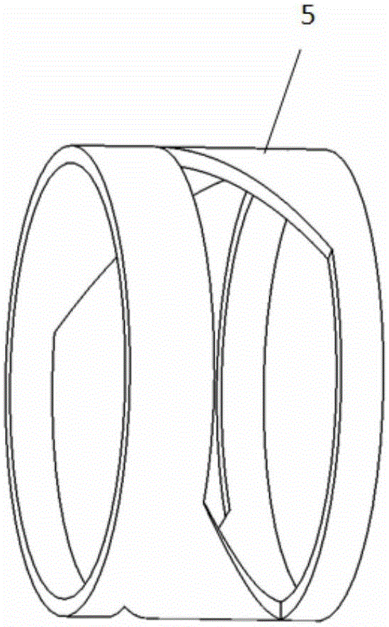
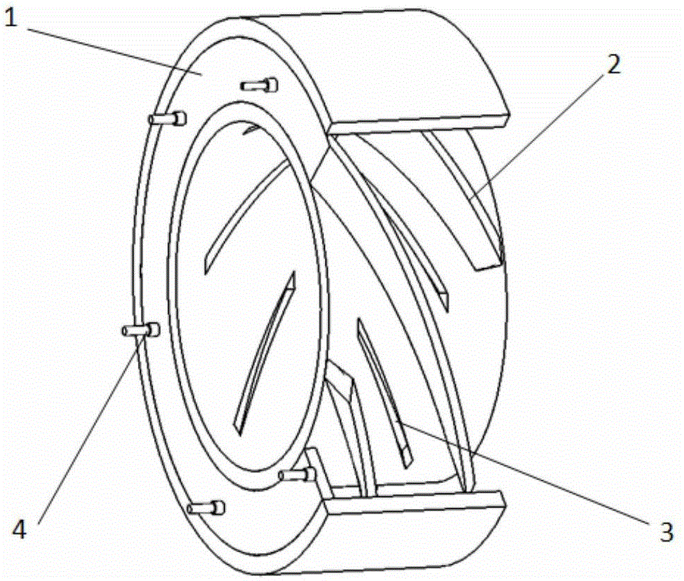
[0020] refer to figure 1 , figure 2 , image 3 , the spiral multi-channel pulse detonation engine of this embodiment is composed of an engine casing 1, a spiral partition 2, an air intake slot 3, a spark plug 4, and an intake rotor 5; the engine casing 1 is a ring structure, and the outer One end of the cavity formed by the ring and the inner ring is sealed, and the spiral partition 2 is fixed on the inner ring wall of the annular cavity. The spiral partition 2 is evenly distributed along the circumference of the inner ring wall to isolate the annular cavity into 2n spiral detonation channels. Where n≥2, there is a spiral air inlet slot 3 on the inner ring wall between the spiral partitions 2, the guide line of the air intake slot 3 has the same parameters as the guide line of the spiral partition 2, and the parameters of the spiral guide line include the pitch , radius, and two helical guide line...


PUM


Abstract

The invention discloses a spiral multi-channel pulse detonation engine which comprises an engine shell, spiral partition plates, gas inlet slots, a plurality of spark plugs and a gas inlet rotor. The engine shell is circular, the spiral partition plates are fixed onto an inner ring wall of an annular cavity to form spiral channels, and the gas inlet slots are formed in the inner ring wall and are positioned among the spiral partition plates; two spiral slots which are in identical shapes are formed in the gas inlet rotor and are used as common gas inlet channels. The gas inlet rotor is in close fit with an inner ring of the engine shell and can freely rotate. The multiple spark plugs are mounted at the ends of the engine, are correspondingly matched with the spiral channels on the inner ring wall and are controlled by a computer, an automatic ignition effect can be realized according to the rotational speed of the gas inlet rotor and phase of the gas inlet channels, and accordingly a multi-tube time-sharing initiation effect can be realized. The spiral multi-channel pulse detonation engine has the advantages that a low-energy ignition mode is adopted by the engine, so that axial DDT (deflagration to detonation transition) distances can be shortened, and the spatial size of the engine can be effectively utilized; the gas inlet slots are formed in positions along a detonation chamber, and gas can flow into the spiral multi-channel pulse detonation engine via the gas inlet slots, so that the spiral multi-channel pulse detonation engine is short in filling time and high in gas inlet filling speed, and the detonation frequency can be increased.

Description

technical field [0001] The invention belongs to the field of pulse detonation engines, in particular to a helical multi-channel pulse detonation engine. Background technique [0002] The discovery of detonation waves can be traced back to the end of the 19th century. Compared with slow combustion waves, the propagation speed of detonation waves can reach several kilometers per second, and at the same time, extremely high gas pressure and gas temperature are generated. Due to the supercharging of detonation combustion waves Effects, theoretical calculations and test results show that the propulsion performance of the pulse detonation engine is much higher than that of the existing traditional engines. [0003] In order to obtain a high-performance pulse detonation engine, how to obtain the detonation wave at a shorter distance and increase the detonation frequency of the pulse detonation engine is the core problem to be solved; compared with the pulse detonation engine, the r...

Claims


Application Information

Patent Timeline
Patent Type & Authority Patents(China)
IPC IPC(8): F02K7/02F02K9/60
Inventor 邱华郑龙席熊姹郑华雷
Owner NORTHWESTERN POLYTECHNICAL UNIV
Learn More