Eureka AIR delivers breakthrough ideas for toughest innovation challenges, trusted by R&D personnel around the world.

Electromagnetic valve and connector thereof

A technology of connectors and solenoid valves, applied in valve details, valve devices, valve operation/release devices, etc., can solve the problem of coil failure, small pressing force of the second seal 101 and the first seal 104, and failure To the sealing effect and other issues, to reduce the risk of damage, guarantee the sealing effect and prolong the service life

Active Publication Date: 2014-07-02
浙江三花商用制冷有限公司
View PDF6 Cites 2 Cited by
  • Summary
  • Abstract
  • Description
  • Claims
  • Application Information

AI Technical Summary

Problems solved by technology

[0007] On the one hand, the sealing reliability of the existing connector 10 is poor, and it is difficult to meet the requirements of waterproof and dustproof
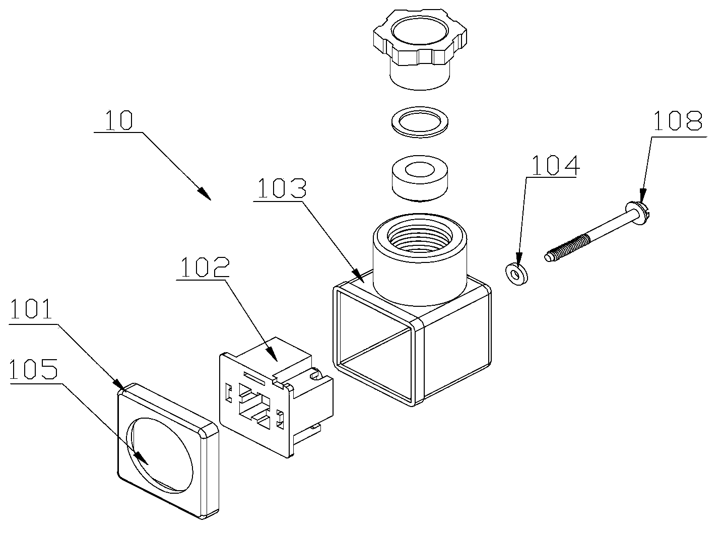
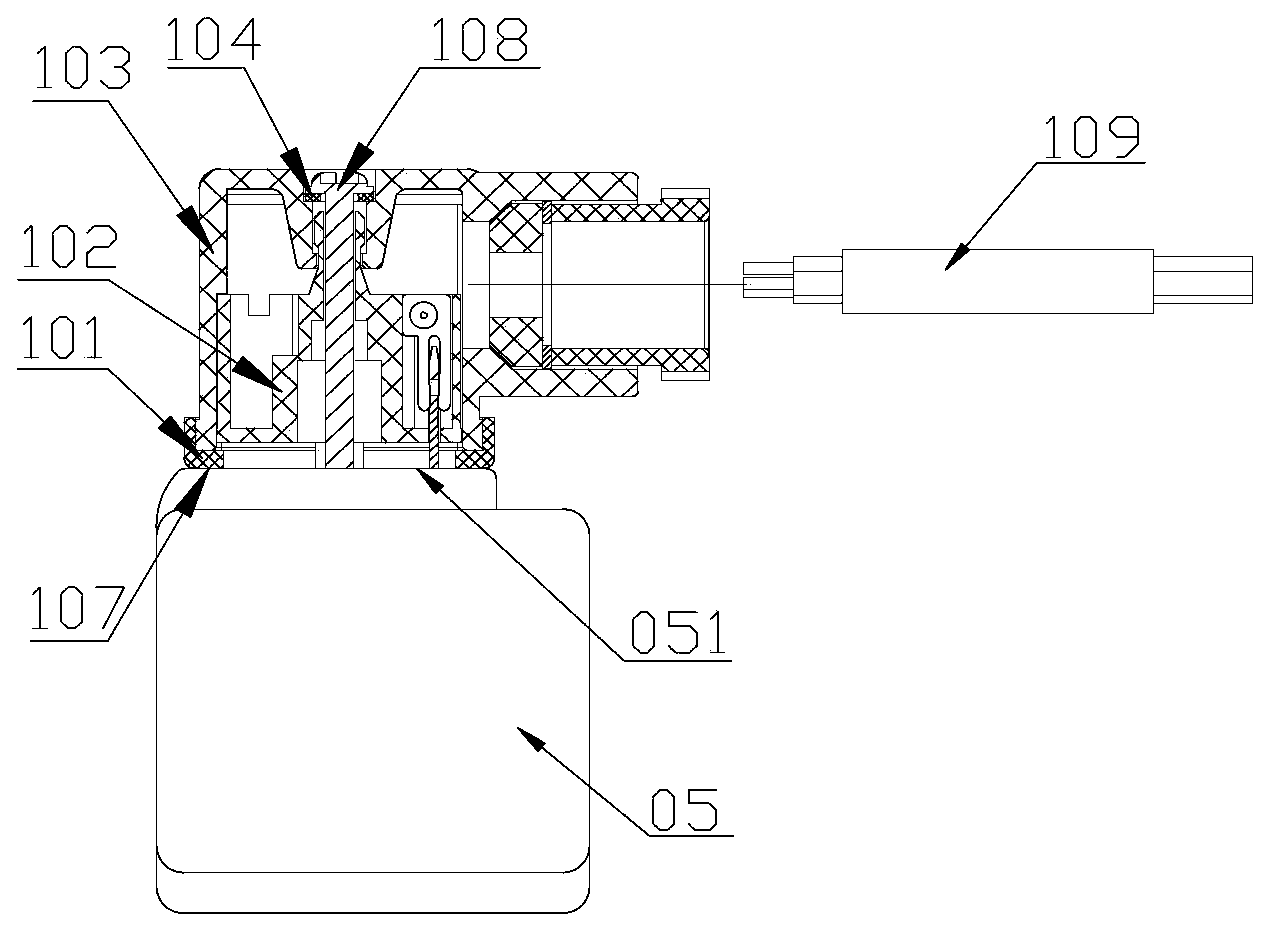
like image 3 As shown, the connection port between the screw 108 of the existing connector 10 and the shell 103, the connection between the socket 102 and the coil 05 are the weak links of its seal, these two parts are most likely to be infiltrated by water or other liquids, and these two places The sealing performance of the seal depends entirely on the locking degree of the screw 108; at the initial stage of being put into use, the screw 108 can compress the second seal 101 and the first seal 104 under the action of a certain tightening force, so that the two are fully deformed , to fill the gap around it to form a sealing layer; after a period of use, the electromagnetic valve coil is more and more obviously affected by the frequent vibration of the system, and the screw 108 is more likely to loosen, and the second seal 101 and the first The compression force on the seal 104 becomes smaller, resulting in the deformation of the two being unable to effectively fill the gap around it, external moisture or other liquids can easily penetrate into the interior of the connector 10, and eventually cause the coil to fail, endangering the safety of the system
[0008] On the other hand, the screw 108 of the existing connector 10 and the screw hole of the socket 102 adopt a clearance fit, and the screw rod of the screw 108 is relatively slender. After the coil is affected by the long-term frequent vibration of the system, the strength of the screw 108 decreases, which is very Fractures may occur, and the second seal 101 and the first seal 104 that lose the connection of the screw 108 do not perform any sealing function at all
[0009] Secondly, the sealing effect between the first sealing member 104 and the screw 108 and the shell 103 is not good enough
Practice has proved that during the locking process of the screw 108, its outer edge will cut the first sealing member 104. If the screw 108 is repeatedly tightened and loosened, the first sealing member 104 will easily be damaged, and then loss of sealing
[0010] Again, the sealing effect between the socket 102 and the coil 05 is not ideal
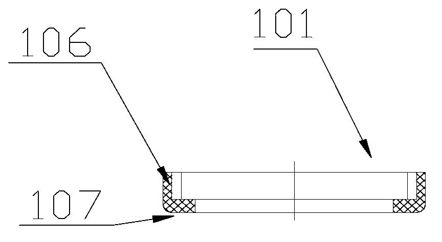
The thickness of the second sealing member 101 is small, and its bottom surface 107 is comparatively flat, so the compression space of the second sealing member 101 is relatively small; If the flat bottom surface 107 of the second sealing member 101 is completely pressed onto the end surface 051 of the coil 05, the deformation of the second sealing member 101 may not be able to completely fill the surrounding gap, thereby affecting the waterproof and dustproof performance of the connector 10.
[0011] In addition, the above-mentioned existing connector 10 includes many parts, and its assembly process is relatively complicated. During the installation process of the screw 108, there is a hidden danger of missing the first sealing member 104

Method used


Image

  • Electromagnetic valve and connector thereof
  • Electromagnetic valve and connector thereof
  • Electromagnetic valve and connector thereof

Examples


Embodiment Construction

[0045] The core of the present invention is to provide a connector for a solenoid valve, which can avoid contact collision between adjacent terminals and avoid short circuit.

[0046] Another core of the present invention is to provide a solenoid valve with the above-mentioned connector, which has high connection reliability and is safer and more convenient to use.

[0047] In order to enable those skilled in the art to better understand the solution of the present invention, the present invention will be further described in detail below in conjunction with the accompanying drawings and specific embodiments.

[0048] Please refer to Figure 5 with Image 6 , Figure 5 It is a schematic diagram of assembly and disassembly of the electromagnetic valve provided by the present invention in a specific embodiment; Image 6 for Figure 5 Assembled complete cross-sectional view of the structure shown.

[0049] In a specific embodiment, the solenoid valve of the present invention...


PUM

PropertyMeasurementUnit
Depthaaaaaaaaaa

Abstract

The invention provides an electromagnetic valve and a connector thereof. The electromagnetic valve provided with a coil high in sealing reliability is safer and more convenient to use. The connector comprises a shell and a first sealing part with a through hole, a socket internally sleeves the shell and in inserted connection with an insertion piece of the coil of the electromagnetic valve, and the shell and the insertion piece are hermetically connected and axially positioned through a fastener. The shell and the socket are provided with axially through connection holes, the first sealing part internally sleeves the connection holes, and the head end of the fastener penetrates through the through hole of the first sealing part to be connected with the insertion piece. The first sealing part is provided with a protrusion matched with the tail end of the fastener. When the fastener is locked, a gap between the fastener and the shell is filled with the protrusion, so that sealing is realized, external dust and liquid can be prevented from entering the connector, and effectiveness in water and dust proofing is achieved.

Description

technical field [0001] The invention relates to the technical field of valve body connection, in particular to a connector of an electromagnetic valve. The present invention also relates to a solenoid valve using the above-mentioned connector. Background technique [0002] The connector of the solenoid valve is a device used to assemble and connect with the solenoid valve coil so that the protection level of the coil meets certain requirements. Usually, commercial solenoid valve coils are more demanding in use environment and conditions than household products, and have higher requirements for the safety performance of the coils. It is the most basic requirement for the protection level to meet IP65, which requires solenoid valves to be in Water sprayed in all directions has no harmful effect and no dust can enter. [0003] Please refer to Figure 1-Figure 4 , figure 1 It is a schematic diagram of an exploded structure of a configuration method of a connector of a soleno...

Claims


Application Information

Patent Timeline
IPC IPC(8): F16K31/06
CPCF16K31/0675
Inventor 不公告发明人
Owner 浙江三花商用制冷有限公司
Why Eureka
Eureka Blog
Learn More