Check patentability & draft patents in minutes with Patsnap Eureka AI!

Backlight module

A technology of backlight module and light source, which is applied in the field of backlight module, can solve the problems of reducing light utilization rate, and achieve the effect of avoiding optical loss, improving luminous efficiency, and tight combination

Inactive Publication Date: 2014-07-02
HONG FU JIN PRECISION IND (SHENZHEN) CO LTD +1
View PDF5 Cites 3 Cited by
  • Summary
  • Abstract
  • Description
  • Claims
  • Application Information

AI Technical Summary

Problems solved by technology

However, in this method, there is a gap between the light-emitting diode light sources and the light guide plate, so that some light rays at specific angles cannot enter the light guide plate, resulting in light leakage, thereby reducing the utilization rate of light.

Method used


Image

  • Backlight module
  • Backlight module
  • Backlight module

Examples


Embodiment Construction

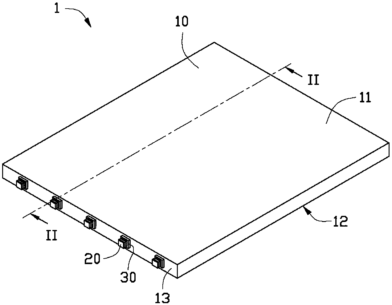
[0013] figure 1 A three-dimensional schematic diagram of a backlight module provided by a preferred embodiment of the present invention. The backlight module 1 includes a light guide plate 10 , a plurality of LED light sources 20 and a transparent glue 30 fixing the plurality of LED light sources 20 to one side of the light guide plate 10 .

[0014] The light guide plate 10 is a thin flat plate, which has an upper surface 11 and a lower surface 12 arranged oppositely and in parallel, and four sides 13 connecting the upper surface 11 and the lower surface 12 . In this embodiment, the side surfaces 13 are perpendicular to the upper surface 11 and the lower surface 12 respectively.

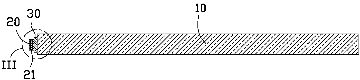
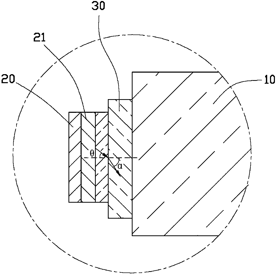
[0015] Please also see figure 2 , the plurality of LED light sources 20 are disposed on one side 13 of the light guide plate 10 , and are all fixed to the same side 13 by glue 30 . The LED light source 20 includes a light-emitting layer 21 inside, and the light emitted by the LED light source 20 ...


PUM


Abstract

A backlight module comprises a light guide plate, a plurality of light-emitting diode light sources arranged in the side direction of the light guide plate, and a glue body fixing the light-emitting diode light sources to the light guide plate.

Description

technical field [0001] The invention relates to a backlight module, in particular to a backlight module which improves the utilization rate of light. Background technique [0002] Compared with traditional light sources, light emitting diodes (Light Emitting Diode, LED) have the advantages of light weight, small size, low pollution, long life, etc. As a new type of light source, it has been increasingly used in in various fields. [0003] However, the backlight module of the liquid crystal panel generally includes a light guide plate and a plurality of LED light sources disposed on one side of the light guide plate. The plurality of light emitting diode light sources are generally fastened to the light guide plate through a mechanism with a plastic frame. However, in all these methods, there is a gap between the plurality of LED light sources and the light guide plate, so that some light rays at specific angles cannot enter the light guide plate, resulting in light leakage...

Claims


Application Information

Patent Timeline
Patent Type & Authority Applications(China)
IPC IPC(8): F21S8/00F21V19/00G02F1/13357F21Y101/02F21Y115/10
Inventor 林辰翰
Owner HONG FU JIN PRECISION IND (SHENZHEN) CO LTD
Features
  • R&D
  • Intellectual Property
  • Life Sciences
  • Materials
  • Tech Scout
  • Unparalleled Data Quality
  • Higher Quality Content
  • 60% Fewer Hallucinations
Learn More