

Oil fume suction machine and thermal cleaning system for oil fume suction machine
A range hood and thermal cleaning technology, which is applied in the field of kitchen and bathroom appliances, can solve problems such as insufficient flushing capacity and poor cleaning effect, and achieve good cleaning effect
- Summary
- Abstract
- Description
- Claims
- Application Information
AI Technical Summary
Problems solved by technology
Method used
Image

Examples
Embodiment 1
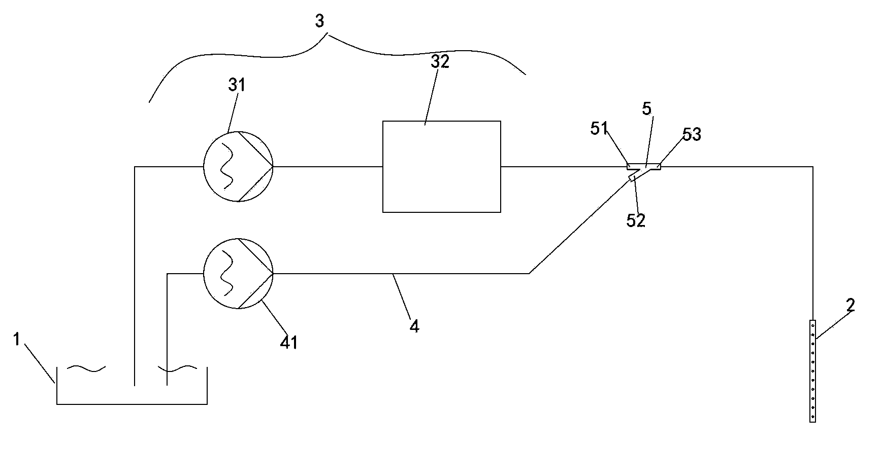
[0061] Such as figure 1 As shown, in this embodiment, the connecting pipe 5 is a first three-way pipe. As mentioned above, the connecting pipe 5 includes a first pipe joint 51, a second pipe joint 52 and a third pipe joint 53, wherein the first pipe joint 51 is the steam inlet, the second joint 52 is the water inlet, and the third pipe joint 53 is the cleaning fluid outlet.
[0062] In this embodiment, the water supply channel 4 includes a second water pump 41 connected between the water tank 1 and the second pipe joint 52 of the connecting pipe to deliver water to the second pipe joint 52 .
[0063] Refer below figure 1 The thermal cleaning process of the thermal cleaning system according to Embodiment 1 of the present invention will be described.
[0064] During the heat cleaning process, the first water pump 31 delivers water to the steam generator 32 at a speed of 50 to 100 mL per minute, and the water delivery pressure is greater than 0.2 MPa. The steam generator 32 he...
Embodiment 2
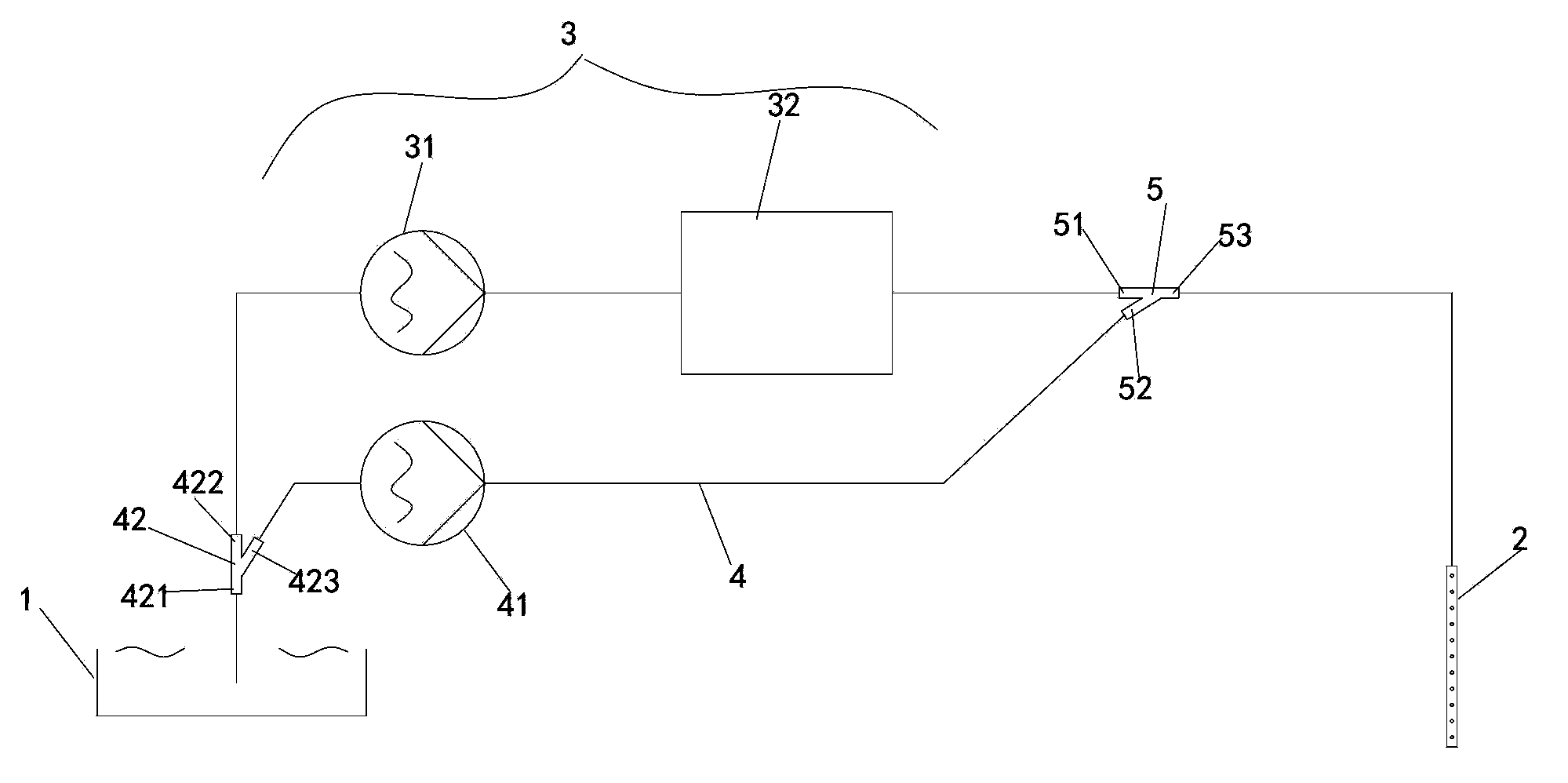
[0067] Such as figure 2 As shown, the difference between this embodiment and Embodiment 1 is that the water supply channel 4 may also include a second three-way pipe 42, and the second three-way pipe 42 has a fourth pipe joint 421, a fifth pipe joint 422 and a sixth pipe joint. The joint 423 and the fourth pipe joint 421 communicate with the water tank 1 , and the fifth pipe joint 422 and the sixth pipe joint 423 are respectively connected with the first water pump 31 and the second water pump 41 .
[0068] Refer below figure 2 The thermal cleaning process of the thermal cleaning system according to the second embodiment of the present invention is described.
[0069] During the heat cleaning process, the first water pump 31 delivers water to the steam generator 32 at a speed of 50 to 100 mL per minute, and the water delivery pressure is greater than 0.2 MPa. The steam generator 32 heats the water into high-temperature and high-pressure steam and outputs it to the first pi...
Embodiment 3
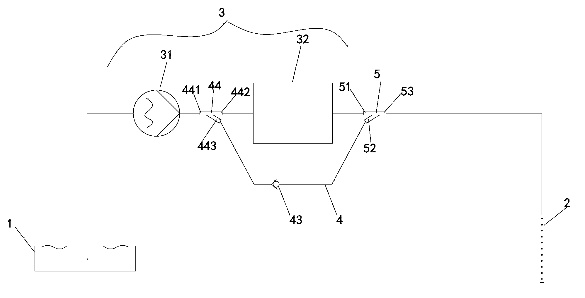
[0072] Such as image 3 As shown, in this embodiment, the connecting pipe 5 is a first three-way pipe. As mentioned above, the connecting pipe 5 includes a first pipe joint 51, a second pipe joint 52 and a third pipe joint 53, wherein the first pipe joint 51 is the steam inlet, the second joint 52 is the water inlet, and the third pipe joint 53 is the cleaning fluid outlet.
[0073] In this embodiment, the water supply channel 4 includes a third three-way pipe 44, the third three-way pipe 44 has a seventh pipe joint 441, an eighth pipe joint 442 and a ninth pipe joint 443, the seventh pipe joint 441 and the eighth pipe joint The pipe joint 442 communicates with the first water pump 31 and the steam generator 32 , and the ninth pipe joint 443 is connected to the second pipe joint 52 of the connecting pipe through the pressure check valve 43 .
[0074] Specifically, the pressure check valve 43 includes a valve body 431 , a valve seat 432 , a moving ball 434 and a spring 435 . ...
PUM
| Property | Measurement | Unit |
|---|---|---|
| Diameter | aaaaa | aaaaa |
| Diameter | aaaaa | aaaaa |
| Diameter | aaaaa | aaaaa |
Abstract
Description
Claims
Application Information