Unit pixel structure for liquid crystal displays

A technology of liquid crystal display and unit pixel, which is applied in the direction of instruments, nonlinear optics, optics, etc. It can solve the problems of reducing the opening area and reducing the transmittance, so as to achieve the effect of reducing the aperture ratio and improving the light transmission efficiency

Active Publication Date: 2014-07-02
NANJING CEC PANDA LCD TECH
View PDF5 Cites 31 Cited by
  • Summary
  • Abstract
  • Description
  • Claims
  • Application Information

AI Technical Summary

Problems solved by technology

The disadvantage of this structure is that the ITO is set in a Fine Slit shape, which reduces the opening area and reduces the transmittance.

Method used


Image

  • Unit pixel structure for liquid crystal displays
  • Unit pixel structure for liquid crystal displays
  • Unit pixel structure for liquid crystal displays

Examples


Embodiment Construction

[0034] Below in conjunction with accompanying drawing and specific embodiment, further illustrate the present invention, should be understood that these embodiments are only for illustrating the present invention and are not intended to limit the scope of the present invention, after having read the present invention, those skilled in the art will understand various aspects of the present invention Modifications in equivalent forms all fall within the scope defined by the appended claims of this application.

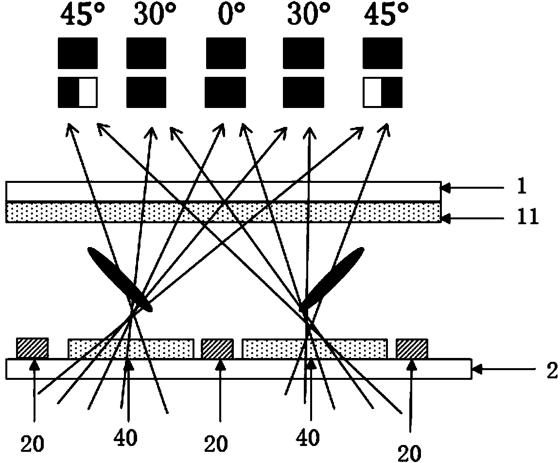
[0035] Figure 9 with Figure 10 Shown is the unit pixel structure of the liquid crystal display of the present invention. The liquid crystal display includes an opposite array substrate, a color filter substrate, and a liquid crystal interposed between the array substrate and the color filter substrate. The array substrate includes: criss-crossing scanning lines 10 and data line 20, active layer 30, pixel electrode 50 defined by the intersection of scan line 10 and dat...


PUM


Abstract

The invention provides a unit pixel structure for liquid crystal displays. A liquid crystal display comprises an array substrate, a color film substrate, and liquid crystal; the array substrate and the color film substrate face each other; the liquid crystal is arranged between the array substrate and the color film substrate; the liquid crystal is in a UV vertical alignment mode; the array substrate comprises scan lines, data lines and pixel electrodes; the scan lines and the data lines intersect crisscross; the pixel electrodes are limited by the scan lines and the data lines intersecting; black lines occur to a pixel electrode area due to UV vertical alignment; the edge of the pixel electrodes is partially provided with a radial slit pattern protruding out. The unit pixel structure has the advantages that the edge black lines expand out of the pixel electrodes, force of the ITO fringe field upon liquid crystal molecules moves out, the dark lines are moved out of an aperture area, a Fine Slit structure enables the black lines to move out to be eliminated, load of resistance and capacitance of an array panel is not increased much, aperture ratio is not lowered, and light transmitting efficiency of UV vertical alignment displays is increased.

Description

technical field [0001] The invention relates to a liquid crystal display of UV light vertical alignment mode, in particular to its unit pixel structure. Background technique [0002] UV 2 A (Ultra Violet Vertical Alignment) technology is a VA (Vertical Alignment, vertical alignment) panel technology that uses ultraviolet light (UV=Ultra Violet) to align liquid crystals. Its name comes from the multiplication of ultraviolet UV and VA mode of liquid crystal panels. By importing UV 2 After A technology, the slits and protrusions currently used to control the alignment of liquid crystal molecules in VA mode liquid crystal panels can be omitted, so through UV 2 The aperture ratio, contrast ratio, and response speed of A-technology LCD panels can be improved, and the production process can be greatly reduced. [0003] UV 2 The key of technology A is to develop the polymer material used as the alignment film. The main chain of the polymer on the surface of the alignment film is...

Claims


Application Information

Patent Timeline
Patent Type & Authority Applications(China)
IPC IPC(8): G02F1/1343G02F1/1337
Inventor 李淑君何建国
Owner NANJING CEC PANDA LCD TECH
Why Eureka
Try Eureka