
LED lamp filament piece, manufacturing method of LED lamp filament piece and LED lamp filament piece bulb

A technology for LED filaments and light bulbs, which is applied in lighting and heating equipment, electrical components, circuits, etc. It can solve the problems of difficult large-scale production of LED filaments, low yield, long length of LED filaments, etc., and achieve streamlined SMT placement process, The effect of reducing production cost and rapid prototyping

Inactive Publication Date: 2014-07-02
东莞市华星照明实业有限公司
View PDF5 Cites 13 Cited by
  • Summary
  • Abstract
  • Description
  • Claims
  • Application Information

AI Technical Summary

Problems solved by technology

[0003]In order to make the LED filament have enough brightness when it emits light, dozens of LED chips are connected in series between the electrodes at both ends of the existing LED filament. It meets the requirements of ambient lighting and light output intensity, but the length of the LED filament is relatively long, which is not suitable for fitting into the inside of the traditional bulb shell; and this leads to too much power consumption, not enough energy saving
In addition, when the number of bonding wires increases, problems are likely to occur, resulting in low yields in the production process, making it difficult for LED filaments to be mass-produced

Method used


Image

  • LED lamp filament piece, manufacturing method of LED lamp filament piece and LED lamp filament piece bulb
  • LED lamp filament piece, manufacturing method of LED lamp filament piece and LED lamp filament piece bulb
  • LED lamp filament piece, manufacturing method of LED lamp filament piece and LED lamp filament piece bulb

Examples


Embodiment 1

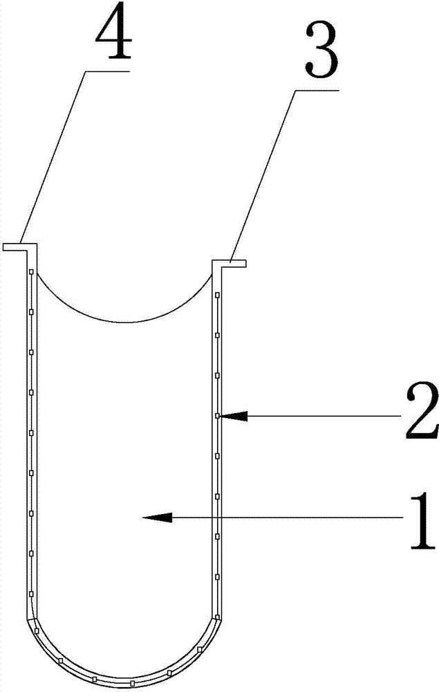
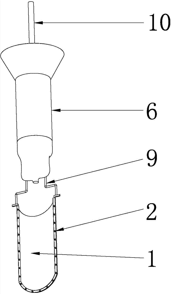
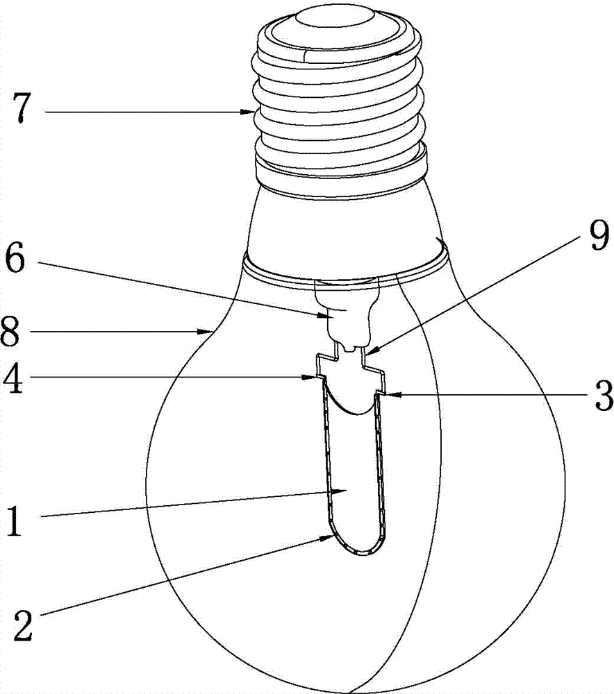
[0038] In this example, please refer to Figure 1 to Figure 5 , provided by the present invention one An LED filament sheet, including a substrate 1, several LED chips 2, and fluorescent glue (not shown in the figure) covering the LED chips 2, the fluorescent glue is composed of a transparent colloidal material mixed with phosphor powder, coated A protective layer of the LED chip 2 is formed on the periphery of the LED chip 2, and an optical lens of the LED chip 2 is formed at the same time, which can increase optical reflection, reduce light loss, and improve light efficiency.

[0039] Several LED chips 2 described in the first embodiment are arranged in sequence according to U-shaped rules and connected in series to form U-shaped LED filaments (such as figure 1 shown), and fixed on at least one side of the substrate 1, in this embodiment, the U-shaped LED filament is only installed on one side, and the side is set outward during use; the substrate 1 A first electrode pin ...


PUM

PropertyMeasurementUnit
Lengthaaaaaaaaaa
Heightaaaaaaaaaa
Diameteraaaaaaaaaa

Abstract

The invention provides an LED lamp filament piece, a manufacturing method of the LED lamp filament piece and an LED lamp filament piece bulb. The LED lamp filament piece comprises a substrate, a plurality of LED wafers and fluorescent glue covering the LED wafers. The LED wafers are sequentially arrayed according to a U shape rule, are in series connection to form a U-shaped LED lamp filament and are fixedly arranged at least one side face of the substrate. A first electrode pin and a second electrode pin are arranged on the substrate, the two ends of the U-shaped LED lamp filament are electrically connected with the first electrode pin and the second electrode pin respectively. According to the LED lamp filament piece bulb, the artistic modeling of a traditional tungsten lamp is inherited, the LED lamp filament piece is used as a lighting source of the bulb, and the advantages of being saving in energy, environmentally friendly and durable are achieved. Due to the fact that the LED wafers of the LED lamp filament piece are in series connection, multiple times of welding is of no need when the LED wafers are manufactured to be the LED lamp filament piece bulb subsequently, an SMT attaching technology is simplified, production cost is lowered, and the LED lamp filament piece, the manufacturing method of the LED lamp filament piece and the LED lamp filament piece bulb are suitable for large-scale production.

Description

technical field [0001] The invention relates to the technical field of LED lighting, in particular to an LED filament sheet, a manufacturing method thereof and an LED filament sheet light bulb. Background technique [0002] A light emitting diode (Light Emitting Diode, LED) is a solid-state semiconductor device that can convert electrical energy into visible light, and it can directly convert electricity into light. The LED light source has the characteristics of energy saving, longevity, environmental protection, solid-state packaging, etc., which determines that LED is the most ideal light source to replace the traditional light source, and has a wide range of uses. At the same time, the LED light panel can realize 360° full-angle light emission, large-angle light emission, and can become a three-dimensional light source, bringing unprecedented lighting experience. [0003] In order to make the LED filament have sufficient brightness when emitting light, dozens of LED chi...

Claims


Application Information

Patent Timeline
IPC IPC(8): H01L33/48H01L33/62F21S2/00F21V23/00F21Y101/02F21K9/232F21K9/90F21Y115/10
CPCF21K9/232F21K9/90F21V19/002F21Y2101/00H01L25/13H01L33/62H01L2933/0066
Inventor 雷剑文
Owner 东莞市华星照明实业有限公司
Learn More