

Movable line protection device
A line protection and mobile technology, applied in the direction of automatic disconnection emergency protection device, emergency protection circuit device, circuit device, etc., can solve the problem of affecting the reliability of power supply, people's normal life, protection can not work normally, and line outage time is long To achieve the effect of increasing power supply reliability, simple installation, and reducing power outage time
- Summary
- Abstract
- Description
- Claims
- Application Information
AI Technical Summary
Problems solved by technology
Method used
Image

Examples
specific Embodiment approach 1
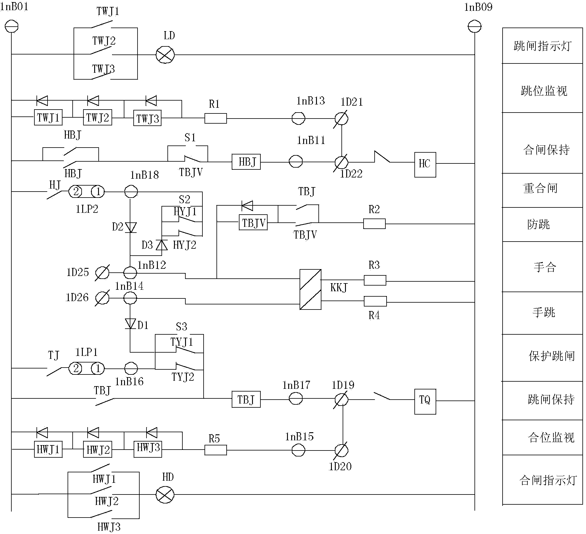
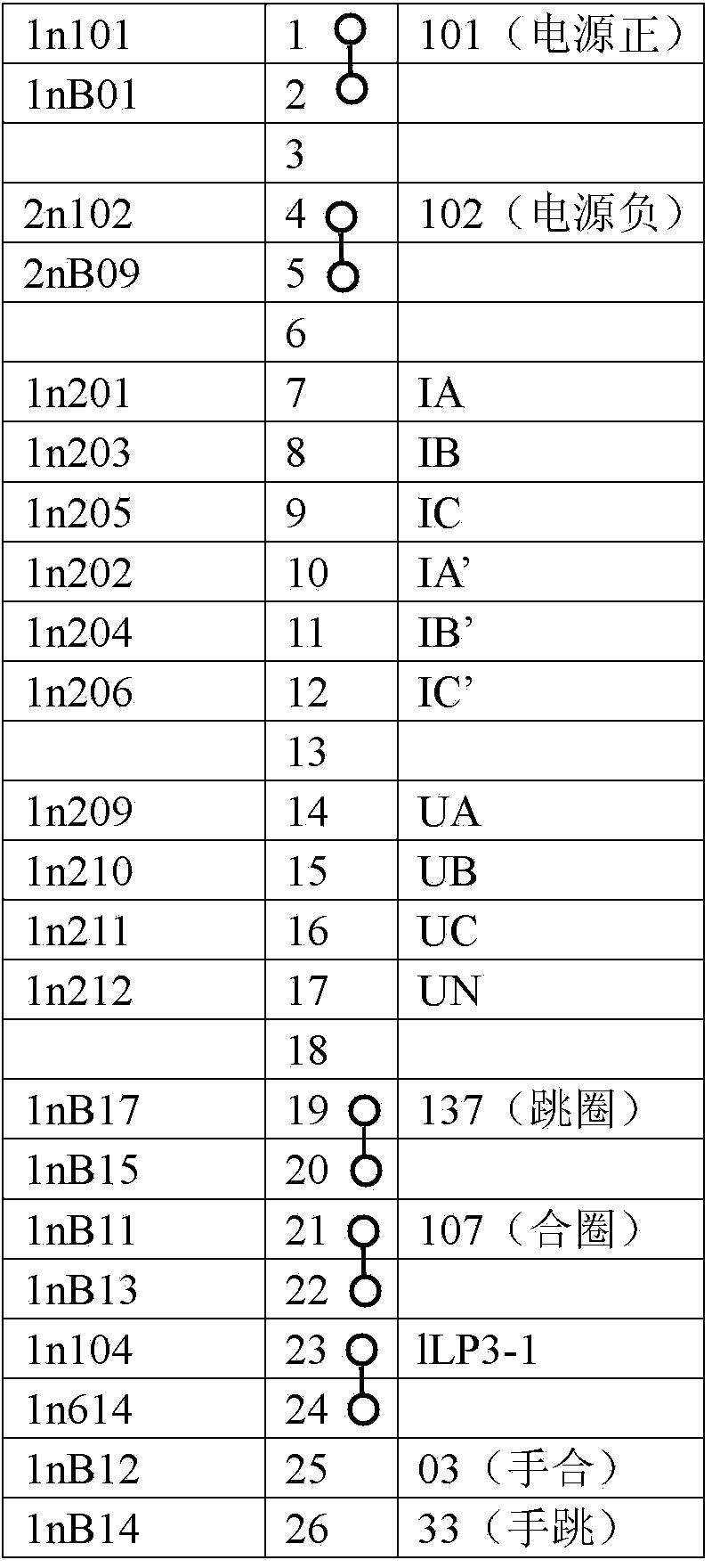
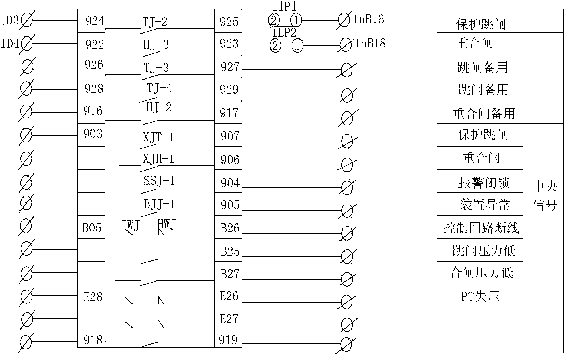
[0031] Specific implementation mode 1. Combination Figure 1-Figure 5 Describe this specific embodiment. The mobile line protection device described in this specific embodiment includes a box body, a terminal block, a pressure plate and a protection circuit. One side of the box body is a panel, and the terminal block and the pressure plate are installed on the side of the box body. On the panel, the protection circuit is fixed inside the box, and the protection circuit includes a voltage and current circuit, an outlet plate and an operation circuit.
[0032] The operation circuit includes the first trip position relay TWJ1, the second trip position relay TWJ2, the third trip position relay TWJ3, the closing holding relay HBJ, the voltage type anti-jumping locking relay TBJV, the closing contactor HC, and the closing relay HJ , Closing pressure locking relay HYJ, trip holding relay TBJ, closing position relay KKJ, tripping pressure locking relay TYJ, trip coil TQ, trip indicato...
specific Embodiment approach 2
[0050] Specific embodiment two, combine figure 1 This specific embodiment is described. The difference between this specific embodiment and the mobile line protection device described in the first specific embodiment is that the coil of the first trip position relay TWJ1, the coil of the second trip position relay TWJ2 and the third trip position The position relays TWJ3 are all connected in parallel with a diode, and the cathode of the diode is connected to the positive busbar 1nB01 of the power supply.
specific Embodiment approach 3
[0051] Specific embodiment three, combine figure 1 This specific embodiment is described. The difference between this specific embodiment and the mobile line protection device described in Embodiment 1 is that the coil of the first closing position relay HWJ1, the coil of the second closing position relay HWJ2 and the second The coils of the three-close position relay HWJ3 are all connected in parallel with a diode, and the cathode of the diode is connected to the positive busbar 1nB01 of the power supply.
PUM
 Abstract
Description
Claims
Application Information