A kind of oled mosaic display screen and manufacturing method thereof

A technology of display screen and front panel, which is applied in the field of OLED splicing display screen and its manufacturing. It can solve the problems of complex preparation process of large-size display devices, difficulty of OLED light-emitting board, and difficult elimination of splicing gaps, etc., so as to increase display aperture ratio and reduce Cost, the effect of increasing the effective light-emitting area

Active Publication Date: 2017-05-17
SHENZHEN ROYOLE TECH CO LTD
View PDF6 Cites 0 Cited by
  • Summary
  • Abstract
  • Description
  • Claims
  • Application Information

AI Technical Summary

Problems solved by technology

The existing commonly used OLED display technology is mainly to directly prepare OLED light-emitting pixel units on the prepared TFT drive substrate, but it is very difficult and costly to prepare a large-area OLED light-emitting panel. , the preparation cost will increase exponentially, and the yield rate will also decrease
[0003] The existing technology mostly adopts the way of splicing display screens to directly splice multiple display screens with ultra-narrow borders. Due to the existence of the row / column scanning drive circuit at the edge of the display screen, it is still impossible to truly achieve "seamless" splicing. The existing technology also has The optical lens array is used to enlarge the image to the border area of ​​the splicing screen to achieve seamless display, but the use of optical lenses and precise alignment increase the manufacturing cost and reduce the yield rate, which makes the manufacturing process of large-size display devices more complicated and costly. higher
[0004] To sum up, the large-size splicing OLED display in the prior art still has the problems of difficult to eliminate the splicing gap and low yield rate.

Method used


Image

  • A kind of oled mosaic display screen and manufacturing method thereof
  • A kind of oled mosaic display screen and manufacturing method thereof
  • A kind of oled mosaic display screen and manufacturing method thereof

Examples


Embodiment Construction

[0025] In order to make the object, technical solution and advantages of the present invention clearer, the present invention will be further described in detail below in conjunction with the accompanying drawings and embodiments. It should be understood that the specific embodiments described here are only used to explain the present invention, not to limit the present invention.

[0026] The present invention will be described in more detail below through specific examples.

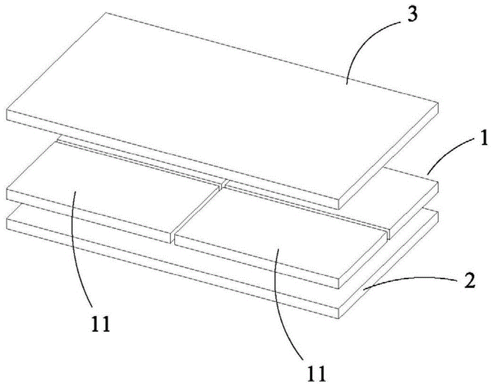
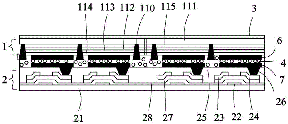
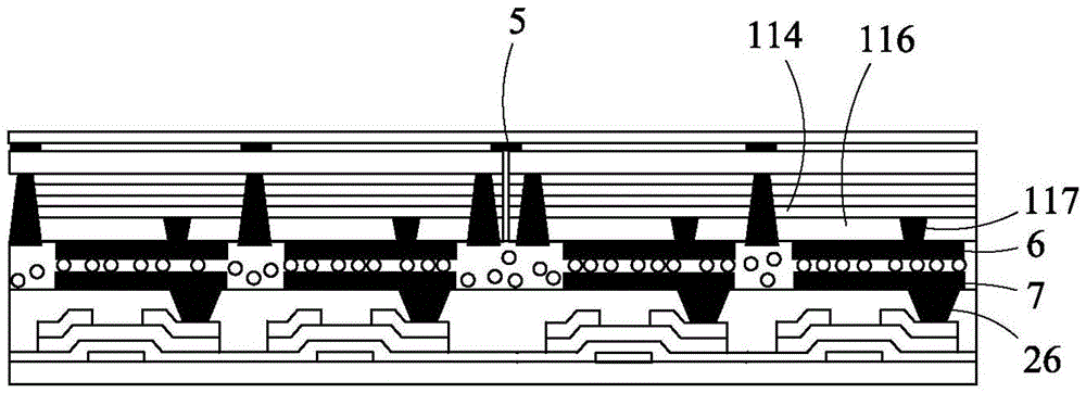
[0027] figure 1 A schematic diagram of the three-dimensional structure of the OLED splicing display screen of the present invention is shown, figure 2 , 3 , 4 respectively show the side views of the first, second and third structures of the OLED splicing display provided in this embodiment, and for the convenience of description, only the parts related to this embodiment are shown.

[0028] Such as figure 1 , 2 , the OLED spliced ​​display screen includes an OLED front panel 1 and a TFT driving ba...


PUM


Abstract

An OLED mosaic display suitable for the field of display technology, comprising an OLED front panel (1) and a single-structure TFT drive backplane (2), and a packaging substrate (3) is also provided on the light-emitting side of the OLED front panel (1) ). The OLED front panel (1) comprises a plurality of mutually spliced ​​OLED front panel units (11). The OLED front panel unit (11) is docked with the TFT driving back panel (2) through a conductive adhesive film. By splicing the OLED front panel unit (11) on the TFT back panel (2), the production efficiency and yield rate of the display screen are improved, and the cost is reduced. Splicing the OLED front panel (1) reduces the splicing gap and can realize seamless splicing. Compared with the traditional structure of using optical lenses to eliminate splicing gaps, the yield rate of splicing display screens is improved. The OLED front plate (1) and the TFT driving back plate (2) are connected by using a conductive adhesive film, thereby increasing the display aperture ratio. And the display screen overcomes the problems of difficult control of alignment accuracy and poor stability.

Description

technical field [0001] The invention belongs to the field of display technology, and in particular relates to an OLED splicing display screen and a manufacturing method thereof. Background technique [0002] At present, most of the display devices based on various display technologies (such as PDP, LCD, OLED, etc.) are limited by their own size, and it is difficult to obtain large-screen displays with low cost and high yield rate at the same time, which affects high-performance, large-screen displays. The development of technology has limited the application of display technology in conference rooms, home theaters, outdoor advertising and other fields. Organic electroluminescence (OLED) technology has become an emerging display technology due to its advantages of active light emission, ultra-thin, low voltage, fast response, high brightness, and wide viewing angle. A variety of large-screen and high-definition OLED display products have entered the flat-panel display market...

Claims


Application Information

Patent Timeline
Patent Type & Authority Patents(China)
IPC IPC(8): H01L27/32H05B33/10
CPCH10K59/127H10K59/1275H10K59/18H10K59/126H10K59/1201H10K59/123H10K59/131
Inventor 余晓军魏鹏刘自鸿
Owner SHENZHEN ROYOLE TECH CO LTD
Why Eureka
Try Eureka