Inductance coil wire pin automatic straightener

A technology of inductance coils and wire needles, which is applied in the field of automatic straightening devices for inductance coil wires, can solve the problems of increased labor costs, poor manual operation accuracy, and high costs, and achieves improved automation, low work intensity, and simple work Effect

Active Publication Date: 2015-11-11
合肥云路聚能电气有限公司
View PDF10 Cites 4 Cited by
  • Summary
  • Abstract
  • Description
  • Claims
  • Application Information

AI Technical Summary

Problems solved by technology

[0005] It can be seen from the above description that the method of straightening the wire pins of the inductance coil in the prior art has the following defects: 1. The manual operation is poor in accuracy and consistency; the perpendicularity of the wire pins to the base cannot be guaranteed, and the verticality of different wire pins cannot be guaranteed. and the straightened pins vary greatly between different workers, between skilled workers and novice hands; 2. The manual operation is heavy and inefficient; for an inductance coil with 4 wire pins, it needs a Holding the inductance coil and straightening it four times with one hand-held clamp, and clamping the wire pins from the bottom end to the free end each time, requires a lot of manpower and a long time. A quantity operator with half a year of work experience , It takes 0.4 hours to straighten 100 four-legged inductance coils continuously; 3. High cost; due to the poor accuracy and poor consistency of manual straightening, there are inferior products, and the manual operation is heavy and inefficient, so the labor cost increases
[0008] Since the wire pin length of the inductance coil is only 4-5cm short, and the material is relatively hard, and the inductance coil has the characteristics of low cost, wide application, small size, and inconvenient operation, the above straighteners are not suitable.
[0009] In the prior art, there is no machine that is small in size, easy to operate, and low in cost, and is suitable for automatically straightening short and small inductance coil wire pins with limited operating space.

Method used


Image

  • Inductance coil wire pin automatic straightener
  • Inductance coil wire pin automatic straightener
  • Inductance coil wire pin automatic straightener

Examples


Embodiment Construction

[0038] The present invention will be described in detail below in conjunction with the accompanying drawings and embodiments.

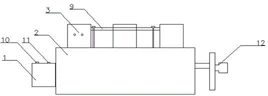
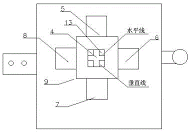
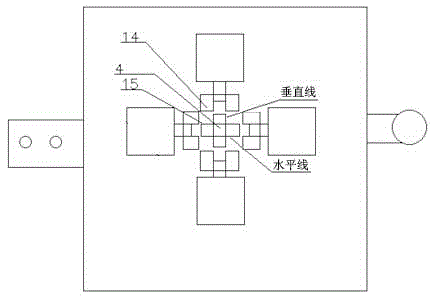
[0039] The technical solution of this embodiment is: an automatic straightening device for inductance coil wire pins, including a controller 1, a straightening part 3 and a fixing part; the straightening part is located above the fixing part; the straightening part includes a Mold core 4 and a plurality of cylinders located around; the upper surface of the mold core is set in a horizontal shape, and pin positions 13 are set around; the number of cylinders, the number of pin positions and the specifications of the mold core are compatible with the specifications of the inductance coil; the cylinder and the mold The core fits together at the stitch position; the cylinder completes the action of clamping the mold core and moving away from the mold core under the control of the controller, thereby straightening the wire stitch 16.

[0040] Among them, the...


PUM

PropertyMeasurementUnit
lengthaaaaaaaaaa

Abstract

The invention relates to straightening machines of pins, in particular to an automatic straightener of inductance oil lead pins. The automatic straightener of inductance oil lead pins comprises a controller, a straightening part and a fixing part. The straightening part is arranged above the fixing part and comprises a die core in the center and a plurality of cylinders around. The upper surface of the die core is horizontal; pin positions are arranged on the periphery of the upper surface of the die core. The cylinders are as many as the pin positions; the die core corresponds to an inductance coil in specification. The cylinders fit the die core at the pin positions. The cylinders clamp the die core and leave the die core under control of the controller, so that the lead pins are straightened. The automatic straightener of inductance oil lead pins has the advantages that the blank of automatic straightener of inductance oil lead pins is filled and increase of automation level is promoted.

Description

technical field [0001] The invention relates to a machine for straightening wire-type stitches, in particular to an automatic straightening device for inductance coil wire stitches. Background technique [0002] The inductance coil is made of wires that are wound round by round on the insulating tube. The wires are insulated from each other, and the insulating tube can be hollow, or it can contain an iron core or a magnetic powder core, referred to as an inductance. The inductance coil is a device that uses the principle of electromagnetic induction to work. When a current flows through a wire, a certain electromagnetic field will be generated around the wire, and the wire itself of this electromagnetic field will induce the wire within the range of this electromagnetic field. The effect on the wire itself that generates the electromagnetic field is called "self-inductance", that is, the changing current generated by the wire itself produces a changing magnetic field, and t...

Claims


Application Information

Patent Timeline
Patent Type & Authority Patents(China)
IPC IPC(8): B21F1/02H01F41/04
Inventor 苏新轩张秀保严文杨乃涛曹民
Owner 合肥云路聚能电气有限公司
Why Eureka
Try Eureka