Graduated adjustable drilling guide tool

An adjustable and guide technology, which is applied in the direction of manufacturing tools, drilling molds for workpieces, clamping, etc., can solve the problems of long processing cycle, long preparation cycle, and high cost, so as to reduce processing costs and improve drilling efficiency , The effect of improving processing efficiency

Active Publication Date: 2014-07-09
HARBIN
View PDF8 Cites 8 Cited by
  • Summary
  • Abstract
  • Description
  • Claims
  • Application Information

AI Technical Summary

Problems solved by technology

If multiple parallel holes need to be drilled, it is difficult to ensure the parallelism of the processed holes and the accuracy of the hole spacing by punching.
Moreover, this drilling

Method used


Image

  • Graduated adjustable drilling guide tool
  • Graduated adjustable drilling guide tool
  • Graduated adjustable drilling guide tool

Examples


Embodiment

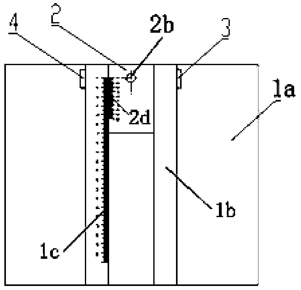
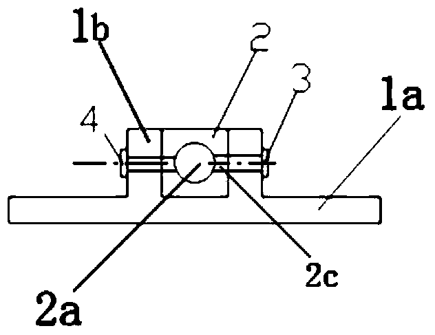
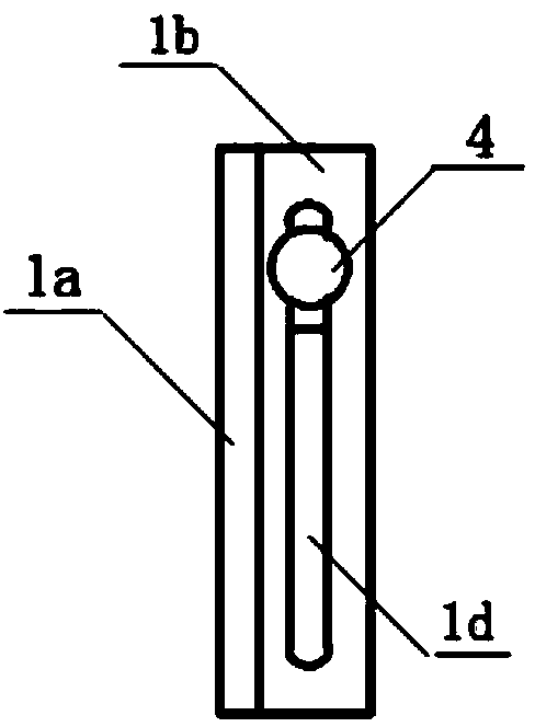
[0014] Combine below Figure 4 to Figure 5 Explain the specific implementation process. The workpiece 5 processes three parallel holes in the axial direction. Hole 5a is 15±0.1mm from the left end of the workpiece, hole 5b is 20±0.1mm from the left end of the workpiece, hole 5c is 28±0.1mm from the left end of the workpiece, and the diameter of workpiece 5 is Φ8f7mm. First, select the slider 2 with the workpiece mounting hole 2a size Φ8H8mm. Then the slider 2 is installed in the base 1, and the workpiece is installed in the workpiece mounting hole 2a of the slider 2. The zero scale line of the main scale 1c on the upper surface of the guide plate 1b is 10 mm from the front end of the base. Move the slider 2 and align the vernier 2d on the slider 2 with the 5mm scale on the main scale 1c. Tighten the slider fastening screw 4 to fix the slider 2 on the base 1, then tighten the workpiece fastening screw 3 to fix the workpiece, and use the drill 6 to drill the hole 5a. Move th...


PUM


Abstract

The invention belongs to machining technology and relates to a graduated adjustable drilling guide tool. The graduated adjustable drilling guide tool is characterized by comprises a base (1), a slider (2), a workpiece fastening screw (3) and a slider fastening screw (4). The graduated adjustable drilling guide tool has the advantages that shaft workpiece drilling precision is guaranteed, machining efficiency is increased, and machining cost is lowered.

Description

Technical field [0001] The invention belongs to mechanical processing technology and relates to an adjustable drilling guide with a scale. Background technique [0002] Drilling on shaft workpieces requires a height gauge for positioning and marking, punching for dots, and V-shaped fixtures for positioning and drilling. If multiple parallel holes need to be drilled, it is difficult to ensure the parallelism of the holes to be machined and the accuracy of the hole spacing by the way of punching. Moreover, this drilling method has a long preparation period and low drilling efficiency. Special drilling tools can also be manufactured for processing, resulting in long processing cycles and high costs. Summary of the invention [0003] The purpose of the present invention is to provide an adjustable drilling guide with a scale to ensure the drilling accuracy of shaft workpieces, improve processing efficiency and reduce processing costs. [0004] The technical solution of the present in...

Claims


Application Information

Patent Timeline
IPC IPC(8): B23B47/28B23Q3/06
CPCB23B47/281
Inventor 陈志龙
Owner HARBIN
Why Eureka
Try Eureka