
Cooling water circulation structure of seam welder

A technology of cooling water circulation and roll welding machine, which is applied in the direction of roller electrode welding, roller electrode, welding equipment, etc., can solve the problems of steel cage corrosion, affecting the quality of steel cage, affecting the working environment, etc., to improve the service life, Effects of saving costs and recycling water resources

Inactive Publication Date: 2014-07-09
江苏中意建材机械有限公司
View PDF0 Cites 4 Cited by
  • Summary
  • Abstract
  • Description
  • Claims
  • Application Information

AI Technical Summary

Problems solved by technology

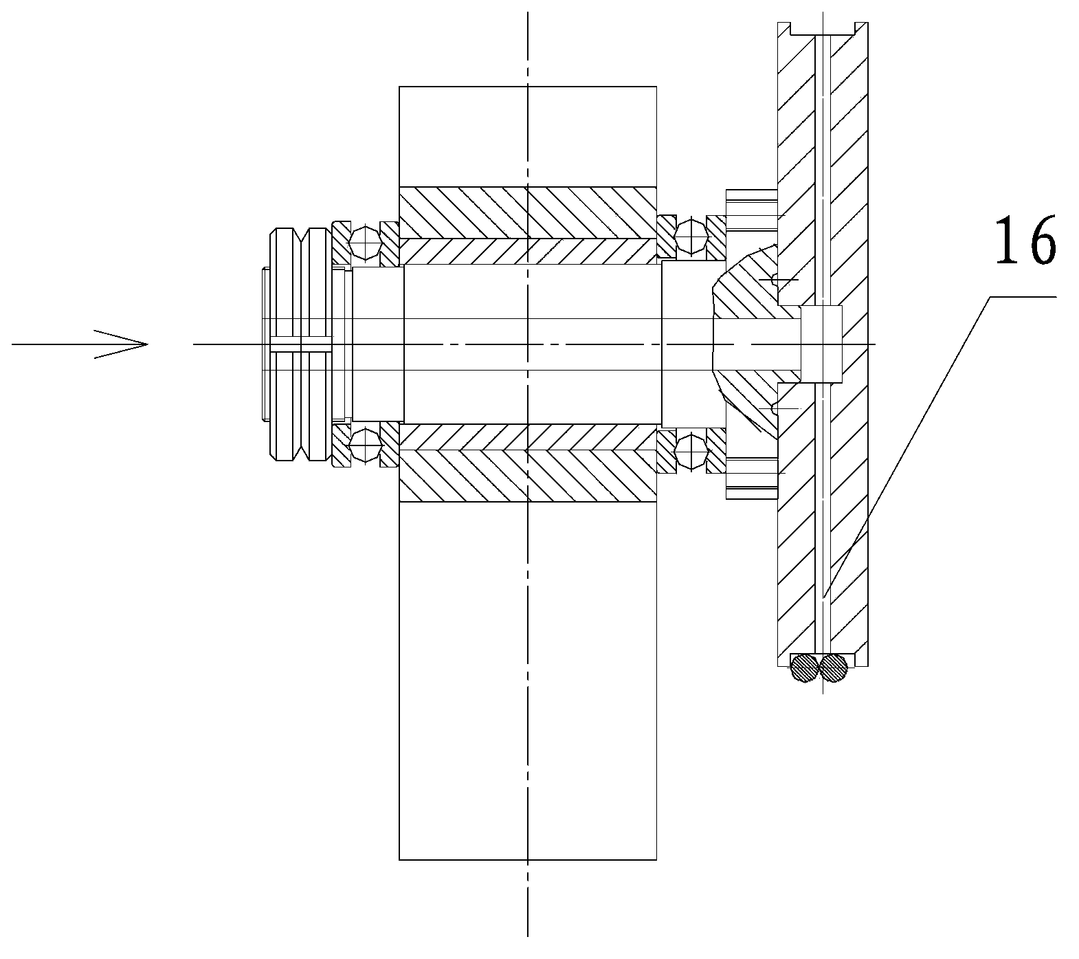
In the prior art, most adopt the straight-through water-cooling structure, and six water channels 16 are arranged on the circumferential surface in the middle of the welding wheel 1, such as image 3 As shown, when the cooling water of this structure is working, because the welding wheel is rotating, the cooling water rotates so that the welding wheel is like a spray head, causing the cooling water to be scattered everywhere, resulting in water accumulation on the work site of the seam welding machine , affecting the working environment; at the same time, the steel cage has been exposed to water for a long time, causing the steel bars of the steel cage to corrode and affecting the quality of the steel cage

Method used


Image

  • Cooling water circulation structure of seam welder
  • Cooling water circulation structure of seam welder
  • Cooling water circulation structure of seam welder

Examples


Embodiment Construction

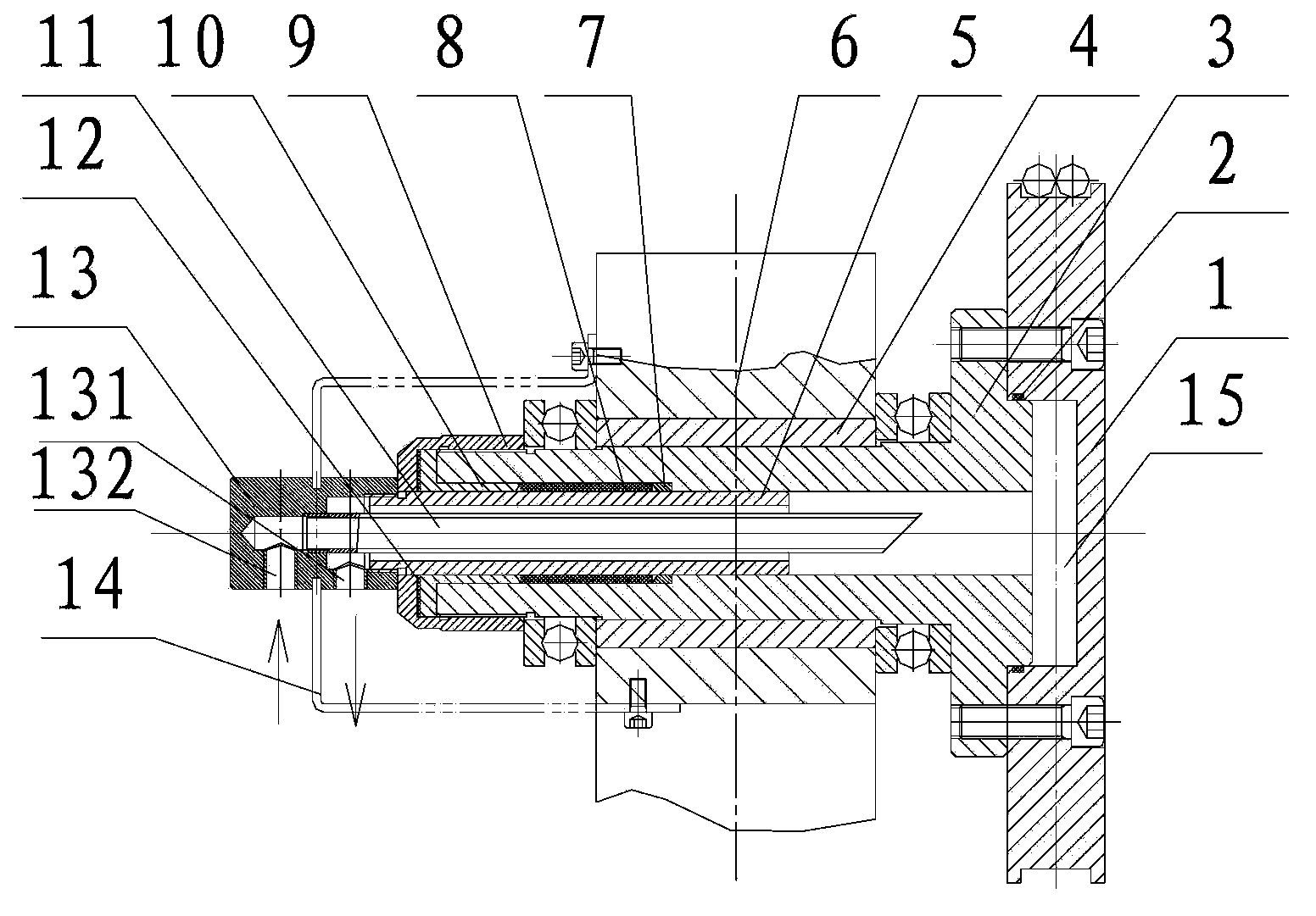
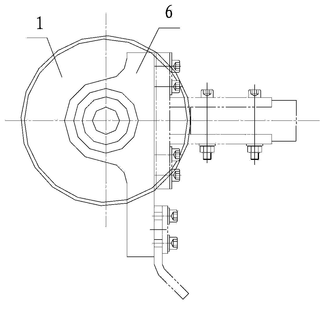
[0019] The invention as Figure 1-2 As shown, the seam welding machine includes a welding wheel 1, an inner cooling head shaft 3 and a welding wheel seat 6 with an axle sleeve 4, the welding wheel 1 and the inner cooling head shaft 3 are coaxial, and the welding wheel 1. Fixedly connect the internal cooling head shaft 3, and the internal cooling head shaft 3 is fixed in the bushing 4 of the welding wheel base 6;

[0020] The inner cooling head shaft 3 is provided with a middle hole, and the end surface of the welding wheel 1 facing the inner cooling head shaft 3 is provided with a cooling hole 15, and the middle hole communicates with the cooling hole 15;

[0021] It also includes a water circulation structure, the water circulation structure is arranged in the middle hole of the internal cooling head shaft 3;

[0022] The water circulation structure includes an outer pipe 5 of the water connection joint and an inner pipe 11 of the water connection joint, and the outer pipe 5...


PUM


Abstract

The invention discloses a cooling water circulation structure of a seam welder, which is simple in structure, is capable of effectively improving the service life of the welding wheel and the use ratio of cooling water, and relates to the improvement of a welding wheel cooling structure of the seam welded. The seam welder comprises a welding wheel, an internal cooling handpiece shaft and a welding wheel seat provided with a shaft sleeve, further comprises a cooling water circulation structure which is arranged in the central hole of the internal cooling handpiece shaft; the cooling water circulation structure comprises a flushing connector outer pipe and a flushing connector inner pipe, and the flushing connector outer pipe is fixedly arranged in the central hole of the internal cooling handpiece shaft; the inner diameter of the flushing connector outer pipe is greater than the outer diameter of the flushing connector inner pipe, and the flushing connector inner pipe is arranged in the flushing connector outer pipe. The cooling water circulation structure is arranged in the central hole of the internal cooling handpiece shaft, and water is fed in the flushing connector inner pipe and drained by the flushing connector outer pipe, so that the heat quantity of the welding wheel can be effectively changed, the water resources can be recycled simultaneously, and the cost can be saved.

Description

technical field [0001] The invention relates to a seam welding machine, in particular to the improvement of the cooling structure of the welding wheel of the seam welding machine. Background technique [0002] When the roll welding machine is working, due to the high welding temperature at the solder joint, the temperature of the welding wheel is also very high, which reduces the service life of the welding wheel. To cool the butt welding wheel, water is usually used for direct cooling. In the prior art, most adopt the straight-through water-cooling structure, and six water channels 16 are arranged on the circumferential surface in the middle of the welding wheel 1, such as image 3 As shown, when the cooling water of this structure is working, because the welding wheel is rotating, the cooling water rotates so that the welding wheel is like a spray head, causing the cooling water to be scattered everywhere, resulting in water accumulation on the work site of the seam weldin...

Claims


Application Information

Patent Timeline
IPC IPC(8): B23K11/36B23K11/06
CPCB23K11/3045
Inventor 仲长平陈兵
Owner 江苏中意建材机械有限公司
Learn More