Device and method for demarcating rearview camera

A calibration device and camera technology, applied in optical observation devices, transportation and packaging, vehicle parts, etc., can solve the problems of high cost and expensive four-wheel alignment station equipment

Active Publication Date: 2014-07-09
GREAT WALL MOTOR CO LTD
View PDF4 Cites 12 Cited by
  • Summary
  • Abstract
  • Description
  • Claims
  • Application Information

AI Technical Summary

Problems solved by technology

Although this method can fix the vehicle well, accurately find the position of the rear-view camera relative to the vehicle and calibrate the camera, the four-wheel alignment station equipment is expensive and the cost is relatively high.

Method used


Image

  • Device and method for demarcating rearview camera
  • Device and method for demarcating rearview camera
  • Device and method for demarcating rearview camera

Examples


Embodiment Construction

[0030] The following will clearly and completely describe the technical solutions in the embodiments of the present invention with reference to the accompanying drawings in the embodiments of the present invention. Obviously, the described embodiments are only part of the embodiments of the present invention, not all of them. Based on the embodiments of the present invention, all other embodiments obtained by persons of ordinary skill in the art without making creative efforts belong to the protection scope of the present invention.

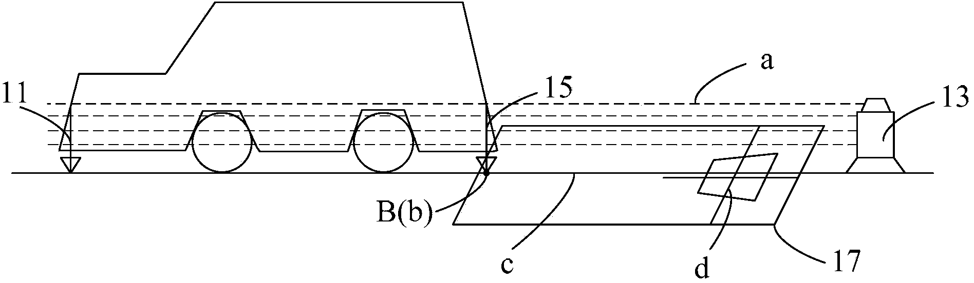
[0031] Such as figure 1 As shown, the embodiment of the present invention provides a rear-view camera calibration device, including: a first plumb 11, the first plumb 11 is fixed on the center line of the vehicle front and vertical to the ground; a laser line throwing device 13, a laser The line throwing device 13 shoots a laser a toward the rear of the vehicle to determine the centerline of the rear of the vehicle. The laser a passes through the...


PUM


Abstract

The invention discloses a device and a method for demarcating a rearview camera, relates to the technical field of automobiles and aims at realizing simplicity in structure and easiness in operation and lowering cost. The device comprises a first plumb, a laser casting device, a second plumb and a target device, the first plumb is fixed on a central line of the head of an automobile and is perpendicular to the ground, the laser casting device casts laser to the tail of the automobile to determine a central line of the tail of the automobile, the laser penetrates a first plumb line to determine a central line of the whole automobile, the second plumb is fixed on the central line, of the tail of the automobile, determined by the laser and overhung to the ground to determine a plumb point, at least one reference point, at least one reference line penetrating each reference point and demarcating patterns are arranged on the target device which is placed on the ground at the tail of the automobile, one of the reference point is coincident with the plumb point, and all of the reference lines are parallel to the laser. The device and the method are suitable for being used in the demarcating process of the rearview camera of the automobile.

Description

technical field [0001] The invention relates to the technical field of automobiles, in particular to a calibration device and method for a rear-view camera. Background technique [0002] At present, rear-view cameras are generally installed at the rear of cars to assist drivers (especially novice drivers) in reversing and parking. [0003] When reversing, the rear view camera transmits the image behind the car to the display screen in front of the driver. The driver can intuitively see the real-time video image behind the car. At the same time, the display screen will display dynamic and static auxiliary lines. The driver can Accurately park the car on the parking space according to these displayed information. However, during the process of processing and installation, the rear view camera may deviate from the standard angle of design, which will cause the position of the image transmitted to the display to deviate from the standard position of the image on the display, th...

Claims


Application Information

Patent Timeline
Patent Type & Authority Applications(China)
IPC IPC(8): B60R1/00
Inventor 赵海龙惠辉高波魏宏王南博
Owner GREAT WALL MOTOR CO LTD
Why Eureka
Try Eureka