Movable dam

A movable and movable dam technology, which is applied in water conservancy projects, sea area engineering, coastline protection, etc., can solve the problems of slow dam lifting speed, easy bursting of dam body, poor impact resistance, etc., and achieves strong anti-flood impact and is not easy to float Sundries, strong impact resistance effect

Active Publication Date: 2014-07-09
江苏恒川水利科技有限公司
View PDF4 Cites 17 Cited by
  • Summary
  • Abstract
  • Description
  • Claims
  • Application Information

AI Technical Summary

Problems solved by technology

Commonly used dams include rubber dams, sluice gates and flap gate dams. Rubber dams are widely used because they are close to the river bed without blocking water, simple in structure, large in span, good in seismic performance, beautiful in shape, and light in weight. , the rubber dam is made of rubber material, which has poor impact resistance, is easy to be scratched by sharp objects, the dam body is easy to burst, and the dam body lifting speed is too slow; although the sluice gate is strong and durable, its construction period is long and the cost is high; the flap door Although the structure of the dam is simple and the construction period is short, it cannot withstand the impact of severe floods, causing it to fail to automatically flap and affect flood control safety. Normal water storage, which makes it impossible to clean up the floating objects, making the river channel dirty and affecting the landscape effect

Method used


Image

  • Movable dam

Examples


Embodiment Construction

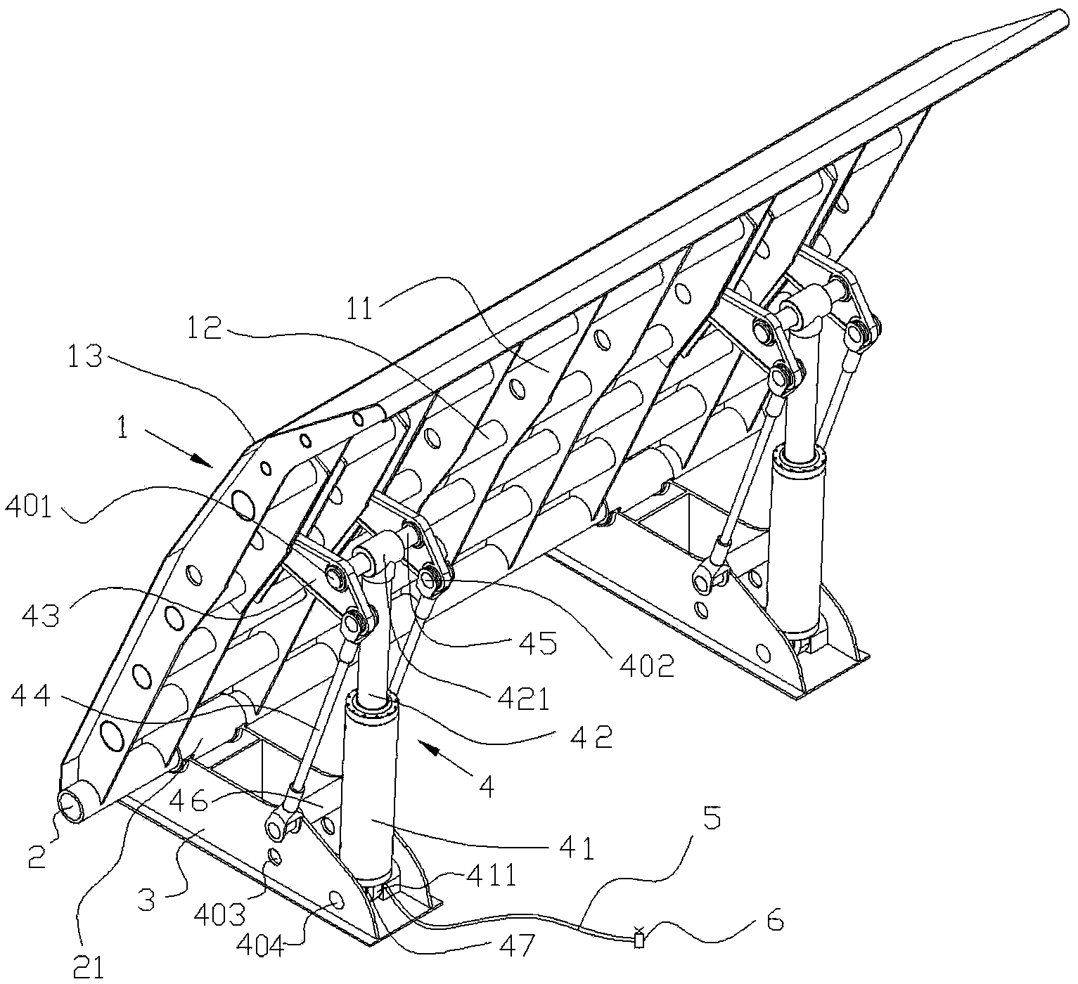
[0018] The present invention will be described in further detail below in conjunction with the accompanying drawings.

[0019] Such as figure 1 As shown, the movable dam includes a movable dam surface 1, a bottom rotating shaft 2 fixedly connected to the movable dam surface 1 by welding or bolts, a fixed seat connector 3, and a hydraulic mechanism 4, and the fixed seat connector 3 is poured on the bottom of the river bed by cement, The bottom rotating shaft 2 is installed on the fixed base connecting piece 3 through the rotating shaft sleeve, and the rotating shaft sleeve 21 is welded on the fixing base connecting piece 3, the movable dam surface 1 rotates through the bottom rotating shaft 2, and the bottom rotating shaft 2 and the rotating shaft sleeve 21 can rotate connect.

[0020] The movable dam surface 1 includes a plurality of steel skeleton ribs 11, a plurality of pin shafts 12 and steel panels 13, each steel skeleton rib 11 is provided with a plurality of pin holes, ...


PUM


Abstract

The invention discloses a movable dam. The movable dam comprises a movable dam face, a bottom rotating shaft, a fixing base connecting piece and a hydraulic mechanism. The bottom rotating shaft is connected to the fixing base connecting piece, the movable dam face rotates through the bottom rotating shaft, one end of the hydraulic mechanism is movably connected with the fixing base connecting piece, and the other end of the hydraulic mechanism is connected with the movable dam face. The hydraulic mechanism comprises a hydraulic cylinder, a piston rod inserted in the hydraulic cylinder, a first connecting piece and a connecting rod, one end, in which the piston rod is not inserted, of the hydraulic cylinder is movably connected with the fixing base connecting piece, one end, which is not inserted in the hydraulic cylinder, of the piston rod is movably connected with the first connecting piece, the first connecting piece is movably connected to the back face of the movable dam face, the first connecting piece is movably connected with one end of the connecting rod, the other end of the connecting rod is movably connected with the fixing base connecting piece, the hydraulic cylinder is further connected with a pipeline, and a valve is arranged on the pipeline. The movable dam is reasonable in structure, firm, reliable, high in flood impact resisting capacity, free of influences of floating sundries and high in dam rising and falling speed.

Description

technical field [0001] The invention relates to the technical field of dams, in particular to a movable hydraulic dam. Background technique [0002] A dam is a water-retaining structure that intercepts the water flow of a river channel to raise the water level or regulate the flow. Reservoirs can be formed to raise water levels, regulate runoff, and concentrate water heads for flood control, water supply, irrigation, hydroelectric power generation, and improved shipping. Commonly used dams include rubber dams, sluice gates and flap gate dams. Rubber dams are widely used because they are close to the river bed without blocking water, simple in structure, large in span, good in seismic performance, beautiful in shape, and light in weight. , the rubber dam is made of rubber material, which has poor impact resistance, is easy to be scratched by sharp objects, the dam body is easy to burst, and the dam body lifting speed is too slow; although the sluice gate is strong and durabl...

Claims


Application Information

Patent Timeline
Patent Type & Authority Applications(China)
IPC IPC(8): E02B7/40E02B7/42
Inventor 牛菊香
Owner 江苏恒川水利科技有限公司
Why Eureka
Try Eureka