Single valve opened engine auxiliary valve actuator
A technology for assisting valves and engines, applied to engine components, machines/engines, mechanical equipment, etc., can solve problems such as difficult to use engines, achieve the effects of reducing load, eliminating influence, and improving performance and durability
- Summary
- Abstract
- Description
- Claims
- Application Information
AI Technical Summary
Problems solved by technology
Method used
Image
Examples
Embodiment 1
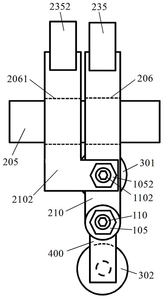
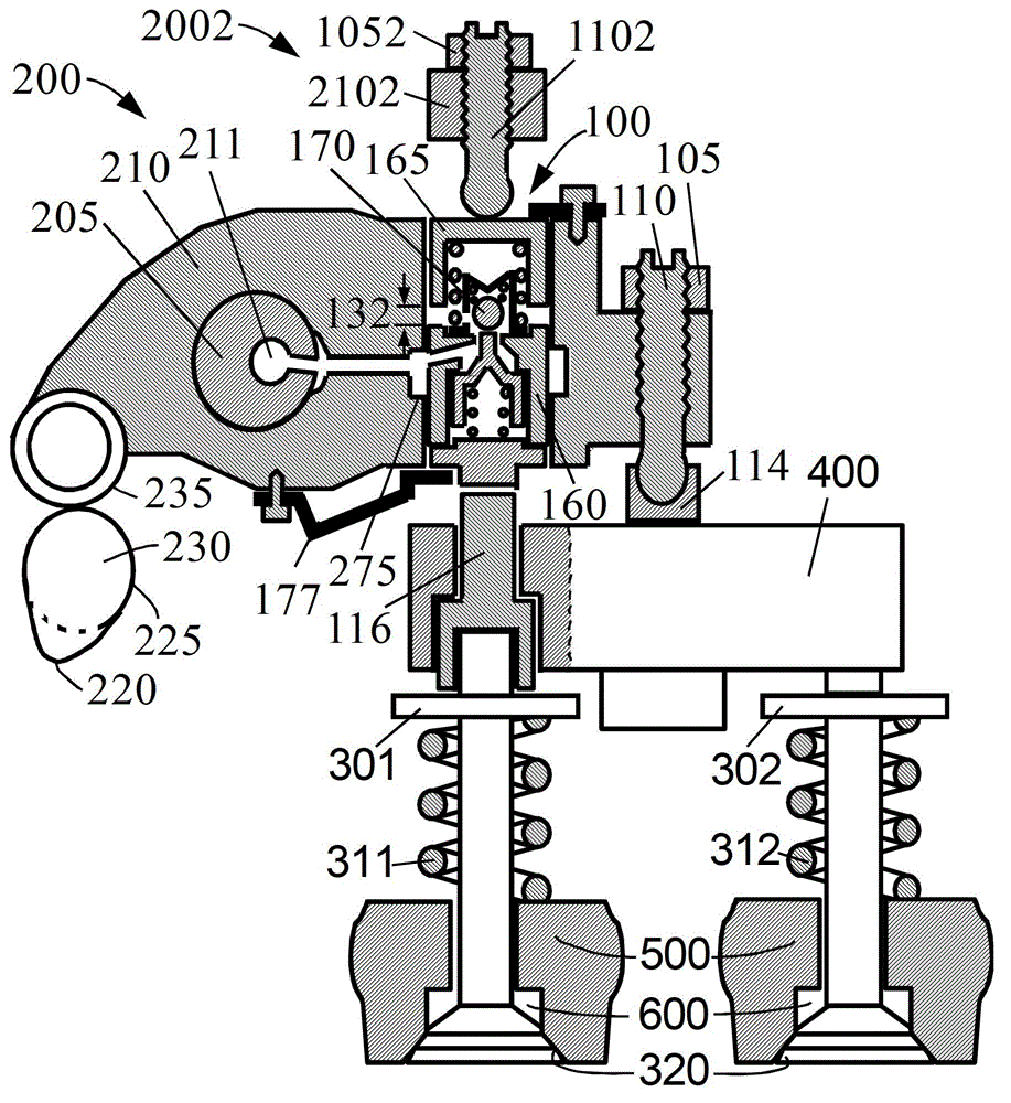
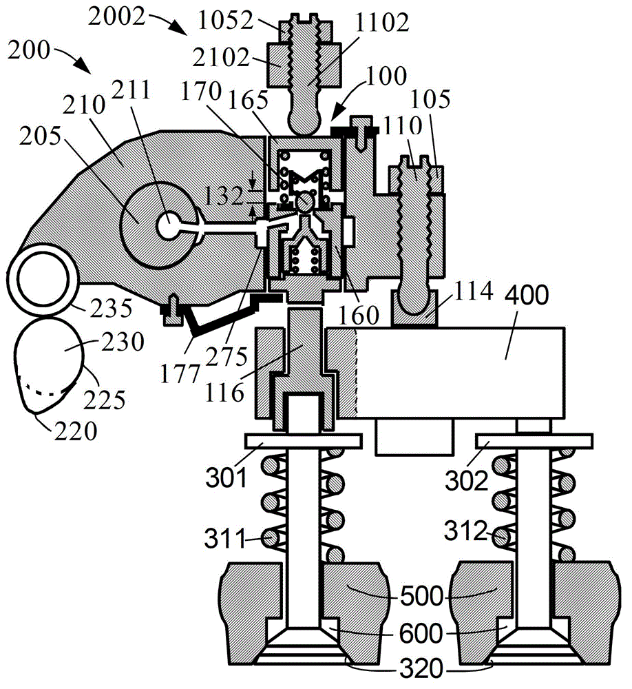
[0040] figure 1 , figure 2 , image 3 and Figure 4 Used to describe Example 1.
[0041] figure 1 The positional relationship between the auxiliary rocker arm 2102 , the conventional rocker arm 210 , the valve bridge 400 and the valves 301 and 302 in Embodiment 1 of the auxiliary valve actuator for a single-valve engine of the present invention is described. First, the valve bridge 400 ( figure 2 and image 3 are more clearly described) located above the engine's two valves 301 (inner valve) and 302 (outer valve). Secondly, the conventional rocker arm 210 is located parallel to the valve bridge 400 (the conventional valve clearance adjusting screw 110 and the lock nut 105 connect the two). Then, the auxiliary valve clearance adjustment screw 1102 and the lock nut 1052 on the auxiliary rocker arm 2102 are located on the conventional rocker arm 210 (while on the inner valve 301). Additionally, the conventional rocker arm 210 (through the conventional rocker hole 206 ) ...
Embodiment 2
[0047] Figure 5 and Figure 6 Used to describe Example 2.
[0048] Figure 5 with embodiment one figure 1 Very similar, the only difference is that the auxiliary rocker arm 2102 of this embodiment is in Figure 4 The mechanism of the shown embodiment one has been increased as Figure 6 Half swingarm shown, supplemented with a support. The two rocker holes 2061 and 2062 of the new auxiliary rocker arm 2102 are installed on both sides of the conventional rocker arm 210 through the conventional rocker shaft 205 ( Figure 5 ). The working principle of this embodiment is the same as that of Embodiment 1, and will not be described in detail here.
Embodiment 3
[0050] Figure 7 and Figure 8 Used to describe embodiment three.
[0051] Figure 7 and Figure 8 with embodiment one figure 2 and image 3 Very similar, the only difference is that the hydraulic control valve 170 of the auxiliary valve clearance compensation mechanism 100 of this embodiment is disposed outside the two pistons 160 and 165 . The working principle of this embodiment is the same as that of Embodiment 1, and will not be described in detail here.
PUM
 Abstract
Description
Claims
Application Information
 - R&D
- Intellectual Property
- Life Sciences
- Materials
- Tech Scout
- Unparalleled Data Quality
- Higher Quality Content
- 60% Fewer Hallucinations
Browse by: Latest US Patents, China's latest patents, Technical Efficacy Thesaurus, Application Domain, Technology Topic, Popular Technical Reports.
© 2025 PatSnap. All rights reserved.Legal|Privacy policy|Modern Slavery Act Transparency Statement|Sitemap|About US| Contact US: help@patsnap.com


