Weld-free type surface mounted device light-emitting diode (LED) lamp structure
A technology of LED lamps and LED lamp beads, which is applied in the direction of lighting devices, cooling/heating devices of lighting devices, light sources, etc., can solve the problems of cumbersome processing procedures, high material costs and processing costs, and single structure, and achieve the optimization of heat dissipation effect , saving material cost, easy and simple installation
- Summary
- Abstract
- Description
- Claims
- Application Information
AI Technical Summary
Problems solved by technology
Method used
Image

Examples
Embodiment 1
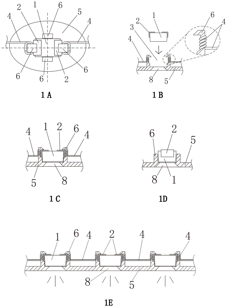
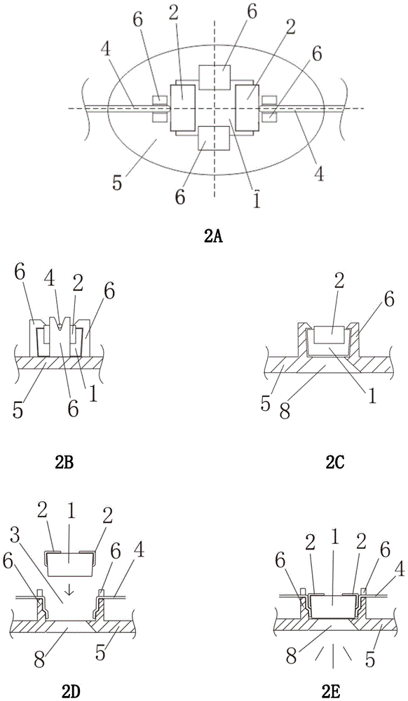
[0055] When a number of LED lamp bead cabins and the substrate are integrated: first, if figure 1 As shown, there are several LED lamp bead cabins (3) distributed on the substrate (5). According to specific needs, each LED lamp bead cabin (3) has a light-transmitting hole (8) at the bottom, and the light-transmitting hole (8) There are several buckles (6) around to fix the LED lamp bead (1), and the two ends of the wire-like connector (4) are respectively wrapped around the LED lights in the two adjacent LED lamp bead cabins (3). Insert the LED light bead (1) into the LED light bead compartment (3) and let the light emitted by the LED light bead (1) pass through the light hole (8). In this way, the pins (2) of the LED lamp beads (1) can be in close contact with the connecting body (4), thereby realizing the electrical connection between adjacent LED lamp beads (1). can also be as figure 2 In the way shown, the metal wire or metal sheet connector (4) is directly and firmly ...
Embodiment 2
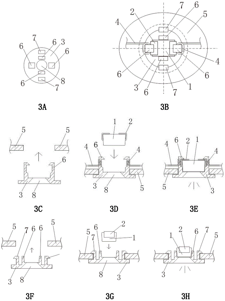
[0057] When several independent LED lamp bead cabins are fixed together through the substrate: first, if image 3 The LED lamp bead compartment (3) shown in 3A has buckles (6) for fixing the LED lamp bead (1) and buckles (7) for fixing the substrate. Such as image 3 In the process shown in 3C-3H, several holes of appropriate size are first opened on the substrate (5), and then the LED lamp bead cabin (3) is fixed on the substrate (5) through the buckle (7), and then used The two ends of the wire-shaped connector (4) are respectively wound on the buckles (6) that the LED lamp bead pins (2) in the two adjacent LED lamp bead cabins (3) can touch, and then the LED lights The bead (1) is embedded in the LED lamp bead cabin (3), and the light emitted by the LED lamp bead (1) passes through the light-transmitting hole (8). In this way, the pins (2) of the LED lamp beads (1) can be in close contact with the connecting body (4), thereby realizing the electrical connection between ad...
Embodiment 3
[0059] Such as Figure 5 , Figure 7 and Figure 8 As shown, several independent LED lamp bead cabins (3) can make the light-emitting surface of the LED lamp bead (1) face up and be embedded in the LED lamp bead cabin (3). Other implementation processes can refer to the corresponding processes of Embodiment 1 and Embodiment 2. In this way, various chain structures of LED lamp bead compartments (3) chains are formed, and the LED lamp bead compartments (3) chains of these several structures can be more flexibly applied to more LED lamps.
PUM
 Abstract
Description
Claims
Application Information
 - R&D
- Intellectual Property
- Life Sciences
- Materials
- Tech Scout
- Unparalleled Data Quality
- Higher Quality Content
- 60% Fewer Hallucinations
Browse by: Latest US Patents, China's latest patents, Technical Efficacy Thesaurus, Application Domain, Technology Topic, Popular Technical Reports.
© 2025 PatSnap. All rights reserved.Legal|Privacy policy|Modern Slavery Act Transparency Statement|Sitemap|About US| Contact US: help@patsnap.com