
Array substrate, manufacturing method and display device

A technology of an array substrate and a manufacturing method, which is applied in the field of display devices, and can solve the problems of affecting the aperture ratio of the display device, reducing the display effect of the display device, and large non-pixel area.

Active Publication Date: 2014-07-09
BOE TECH GRP CO LTD +1
View PDF7 Cites 6 Cited by
  • Summary
  • Abstract
  • Description
  • Claims
  • Application Information

AI Technical Summary

Problems solved by technology

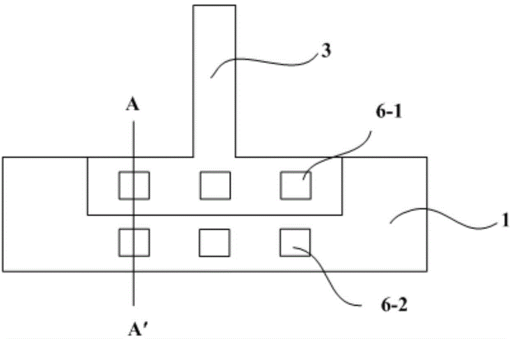
The applicant found that in the prior art, two via holes (6-1, 6-2) are used to connect the first gate lead 1 and the second gate lead 3, resulting in a larger width of the first gate lead 1, The area of ​​the non-pixel area is larger, which affects the aperture ratio of the display device and reduces the display effect of the display device

Method used


Image

  • Array substrate, manufacturing method and display device
  • Array substrate, manufacturing method and display device
  • Array substrate, manufacturing method and display device

Examples


Embodiment 1

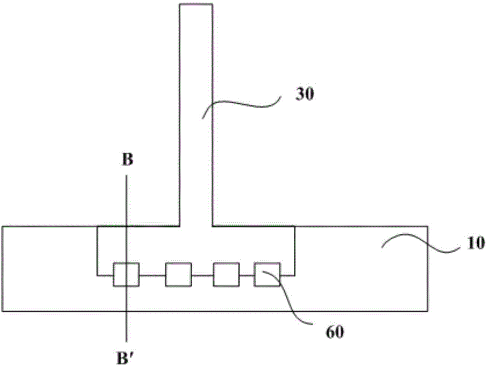
[0060] Step 1. Form the first gate lead 10 on the substrate; specifically, expose and develop the photoresist in the area other than the metal of the first gate lead 10 through a mask, and wet-etch the metal of the first gate lead 10 The metal other than is etched away, leaving the metal of the first gate lead 10;

[0061] Step 2, forming the insulating layer 40 of the first gate lead 10 on the first gate lead 10; directly deposited by plasma enhanced chemical vapor deposition;

[0062] Step 3: Expose and develop the photoresist in the area other than the metal of the second gate lead 30 through a mask, and etch away the metal other than the metal of the second gate lead 30 by wet etching, leaving the second gate lead 30 Metal;

[0063] Step 4, depositing and forming an insulating layer 40 on the first gate lead 10 by plasma-enhanced chemical vapor deposition;

[0064] Step 5: Expose and develop the photoresist at the position of the via hole 60 through a mask, and etch the ...

Embodiment 2

[0068] The array substrate is an array substrate with two transparent conductive layers, and its manufacturing method is as follows:

[0069] Step 1, such as Figure 9a As shown, the first gate lead 10 is formed on the substrate; specifically, the photoresist in the area other than the metal of the first gate lead 10 is exposed and developed through a mask, and the metal of the first gate lead 10 is wet-etched. The metal other than is etched away, leaving the metal of the first gate lead 10;

[0070] Step two, such as Figure 9b As shown, a gate insulating layer 20 is formed on the first gate lead 10; it is directly deposited by plasma enhanced chemical vapor deposition;

[0071] Step three, such as Figure 9c As shown, the photoresist in the area other than the metal of the second gate lead 30 is exposed and developed through a mask, and the metal other than the metal of the second gate lead 30 is etched away by wet etching, leaving the second gate lead 30 Metal;

[0072...


PUM


Abstract

The invention relates to the technical field of display devices, and discloses an array substrate, a manufacturing method and a display device. The array substrate comprises a first grid lead, a second grid lead and a grid insulation layer, wherein the first grid lead and the second grid lead are arranged at the peripheral region of the array substrate, and the grid insulation layer is located between the first grid lead and the second grid lead. The array substrate further comprises a plurality of via holes formed in the first grid lead in an etching mode, the second grid lead is arranged in at least a part of each via hole in a penetrating mode, and first transparent conducting layers for conducting the first grid lead and the second grid lead are arranged in the via holes. The array substrate, the manufacturing method and the display device have the advantages that according to the via hole structure, conduction connection of the first grid lead and the second grid lead can be achieved through a single row of via holes, therefore, the width of the first gird lead can be reduced, the aperture ratio of the display device can be increased, and the display effect of the display device can be enhanced.

Description

technical field [0001] The present invention relates to the technical field of display devices, in particular to an array substrate, a manufacturing method and a display device. Background technique [0002] On the array substrate of the array substrate, there are at least 8 to 10 layers of metal or insulating layers. It is these metal layers and insulating layers that ensure the normal operation of the TFT function on the array substrate and control the display of the array substrate according to the predetermined input signal. In order to connect the same layer of metal or different layers of metal, a large number of via holes are required on the array substrate of TFT-LCD. layer metal. Therefore, in the structural design of the array substrate, the structural design of the via hole is very important. Improving the connection efficiency of via holes and reducing the number of via holes can not only increase the aperture ratio of the array substrate, but also save the spa...

Claims


Application Information

Patent Timeline
Patent Type & Authority Applications(China)
IPC IPC(8): H01L27/12H01L29/786H01L21/77
Inventor 周纪登
Owner BOE TECH GRP CO LTD
Learn More