
A wireless network transceiver device

A technology of wireless network and transceiver devices, applied in the field of wireless network transceiver devices, can solve the problems of high cost of CPE equipment, not suitable for mass promotion, etc., achieve the effect of improving receiving sensitivity, realizing lossless transmission, and improving EIRP index

Active Publication Date: 2016-04-20
KENBOTONG TECH
View PDF4 Cites 0 Cited by
  • Summary
  • Abstract
  • Description
  • Claims
  • Application Information

AI Technical Summary

Problems solved by technology

In the suburbs and rural areas, using CPE client equipment can increase the communication distance to 2 kilometers, but the high cost of CPE equipment is not suitable for mass promotion

Method used


Image

  • A wireless network transceiver device
  • A wireless network transceiver device
  • A wireless network transceiver device

Examples


Embodiment 1

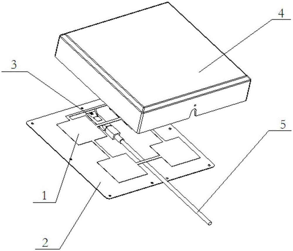
[0030] Such as figure 1 As shown, it is a wireless network transceiver device proposed in this embodiment, including a protective shell 4 for protecting the internal structure, and the inside of the protective shell 4 is packaged with an antenna plate 1, a flat reflector 2, and a wireless network adapter module 3 and cables 5; the antenna board 1 and the wireless network adapter module 3 are both arranged on the flat reflector 2; the radio frequency electrical connection is formed between the wireless network adapter module 3 and the antenna board 1 . The antenna board 1 is a PCB board or a metal structure board; the antenna board 1 includes at least one radiating unit, that is, the antenna board 1 may only include one radiating unit, or may include multiple radiating units.

[0031] Wherein, the structure between the antenna board 1 and the flat reflector 2 constitutes a high-gain directional antenna, and the beam generated by the high-gain directional antenna points to the t...

Embodiment 2

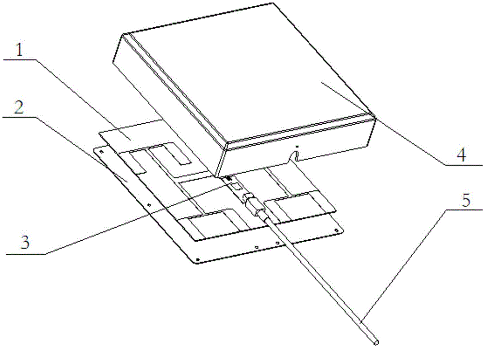
[0048] Such as image 3 As shown, it is a wireless network transceiver device proposed in this embodiment, including a protective shell 4 for protecting the internal structure, and the inside of the protective shell 4 is packaged with an antenna plate 1, a flat reflector 2, and a wireless network adapter module 3 and cables 5; the antenna board 1 and the wireless network adapter module 3 are both arranged on the flat reflector 2; the radio frequency electrical connection is formed between the wireless network adapter module 3 and the antenna board 1 . The antenna board 1 is a PCB board or a metal structure board; the antenna board 1 includes at least one radiating unit, that is, the antenna board 1 may only include one radiating unit, or may include multiple radiating units.

[0049] The antenna board 1 in this embodiment is a PCB board. As a preferred embodiment, the antenna board 1 includes at least two radiating elements; the feeding mechanism and radiator for connecting th...


PUM


Abstract

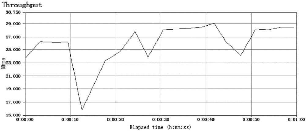
The invention discloses a wireless network transmitter-receiver set which comprises a protective casing for protecting the internal structure. An antenna plate, a plane sheet reflector, a wireless network adapter module and a cable are packaged inside the protective casing; the antenna plate and the wireless network adapter module are both arranged on the plane sheet reflector; the wireless network adapter module is in radio frequency electric connection with the antenna plate. By means of the wireless network transmitter-receiver set, the network access performance with the transmission distance as long as two kilometers and the downlink rate not smaller than 20 Mbps can be provided; in the using process, only standard outdoor type AP devices are needed, transformation is not needed, and cost of the wireless network transmitter-receiver set is only 1 / 3-1 / 2 of the cost of CPE access devices; EIRP indexes of the wireless network adapter module are improved, the receiving sensitivity of the wireless network adapter module is improved, and the functions such as water proofing, dust proofing and ultraviolet proofing are achieved so that the wireless network transmitter-receiver set is suitable for serving as an wireless network access device in countries, outer suburbs and remote regions.

Description

technical field [0001] The present invention relates to the technical field of wireless communication equipment, and in particular to a wireless network transceiver. Background technique [0002] At present, there are two ways to provide users with network access communication in the market: [0003] 1. Wired mode [0004] Common wired technologies include: ADSL based on the telephone network, CABLEMODEM based on the cable broadcasting network, Category 5 Ethernet based on the private network, and fiber-optic-based fiber-to-the-home, etc. [0005] 2. Wireless mode [0006] Common wireless methods include WIFI network based on IEEE802.11 series protocol, GPRS, 3G, 4G and other Internet access methods based on mobile communication network. [0007] The wired method has a large data bandwidth and stable performance, but it needs wiring to enter the home, which requires a large network construction cost and a long construction period. Therefore, the wired method is very suit...

Claims


Application Information

Patent Timeline
Patent Type & Authority Patents(China)
IPC IPC(8): H04B1/40H04B1/38
Inventor 苏光杰宋茂盛卢益文肖鹏程
Owner KENBOTONG TECH
Learn More