LED drive circuit

A LED drive and circuit technology, applied in the direction of lamp circuit layout, electric light source, lighting devices, etc., can solve the problems of input voltage and current phase difference, failure to meet power factor requirements, reduce circuit service life, etc., to reduce volume, Guaranteed power factor performance and improved stability

Active Publication Date: 2014-07-09
成都三零嘉微电子有限公司
View PDF4 Cites 1 Cited by
  • Summary
  • Abstract
  • Description
  • Claims
  • Application Information

AI Technical Summary

Problems solved by technology

Among them, the AC-DC conversion circuit usually adopts a rectification filter circuit or a power factor correction (PFC) switching power supply circuit. The rectification filter circuit will cause the input voltage and current to have a significant phase difference, so that the power factor requirements cannot be met. Power factor correction (PFC) ) The switching power supply circuit uses a power management chip with PFC function, uses a high-frequency transformer and a large capacitor device, although the power factor correction (PFC) switching power supply circuit can achieve a relatively ideal level in performance, but the cost is relatively high
[0004] The filter capacitor 130 is used in the conventional drive circuit, which reduces the service life of the circuit. In the AC-DC conversion circuit 120, a transformer or inductive energy storage element is required, which increases the volume of the circuit. The AC-DC conversion circuit belongs to the switching power supply In the field, the AC-DC converter circuit with power factor correction is more complex

Method used


Image

  • LED drive circuit
  • LED drive circuit
  • LED drive circuit

Examples


Embodiment Construction

[0020] In order to make the object, technical solution and advantages of the present invention clearer, the present invention will be further described in detail below in conjunction with the accompanying drawings and embodiments. It should be understood that the specific embodiments described here are only used to explain the present invention, not to limit the present invention.

[0021] Any feature disclosed in this specification (including any appended claims, abstract and drawings), unless expressly stated otherwise, may be replaced by alternative features which are equivalent or serve a similar purpose. That is, unless expressly stated otherwise, each feature is one example only of a series of equivalent or similar features.

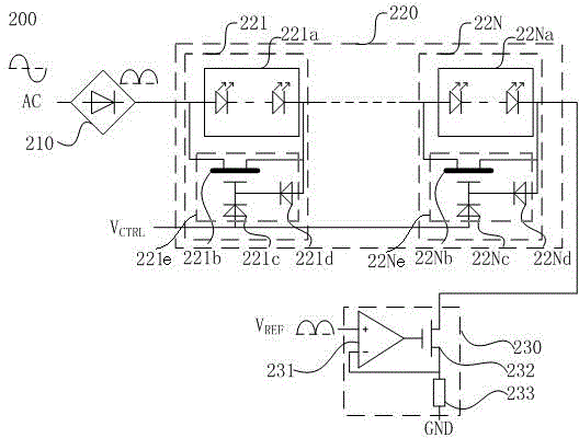
[0022] Such as figure 2 As shown, an LED driving circuit includes a rectifying unit 210 connected in sequence for rectifying the input AC power, a lighting unit 220 for lighting and a current source unit 230 for controlling the current of the lig...


PUM


Abstract

The invention provides an LED drive circuit. The LED drive circuit comprises a rectifying unit (210), an illumination unit (220) and a current source unit (230), wherein the rectifying unit, the illumination unit and the current source unit are sequentially connected, the rectifying unit is used for rectifying input AC voltages, the illumination unit is used for illumination, and the current source unit is used for controlling currents of the illumination unit. The output of the current source unit (230) is connected with the ground wire output of the rectifying unit (210). A large inductor, a capacitor and a power factor correcting circuit are not needed, the illumination unit in the drive circuit is automatically switched on along with the AC power supply voltages, a control circuit is not needed, complexity of the circuit is lowered, the size is effectively reduced, the cost of the circuit is lowered, and the power factor performance of the circuit is guaranteed.

Description

technical field [0001] The invention relates to an LED driving circuit, in particular to an LED lighting driving circuit suitable for AC power supply. Background technique [0002] LED is a semiconductor device driven by a constant current. Compared with traditional light sources such as incandescent lamps, it has many advantages such as high efficiency, small size, and high brightness. Therefore, LED lighting has gradually replaced traditional lighting methods. However, due to the diode characteristics of LEDs, the current flowing through LEDs is exponentially related to its positive voltage drop during forward conduction. Compared with traditional lighting methods, LED lighting requires additional drive circuit. [0003] Such as figure 1 As shown, it is a circuit diagram of a traditional alternating current (AC) power supply LED drive circuit, the drive circuit includes a rectification unit 110, an AC-DC conversion circuit 120, a filter capacitor 130 and an LED lighting ...

Claims


Application Information

Patent Timeline
Patent Type & Authority Applications(China)
IPC IPC(8): H05B37/02
Inventor 冯纯益胡杨川朱翔范伟力廖乾兰程福军
Owner 成都三零嘉微电子有限公司
Why Eureka
Try Eureka