Led lighting heat sink and method for manufacturing same

A technology for LED lighting and heat sinks, which is used in lighting and heating equipment, cooling/heating devices for lighting devices, lighting devices, etc. The effect of cost reduction and high dimensional accuracy

Inactive Publication Date: 2014-07-09
KOBE STEEL LTD
View PDF17 Cites 1 Cited by
  • Summary
  • Abstract
  • Description
  • Claims
  • Application Information

AI Technical Summary

Problems solved by technology

[0013] However, when it is desired to manufacture die-cast heat sinks made of aluminum or an aluminum alloy, etc. as described above, the manufacturing cost increases, and there is also a problem that the heat sink becomes heavy.
Not suitable for use as a heat sink for LED bulbs especially in heavier cases
In addition, in the case of forming many fins on the surface and processing it into a complicated shape, there is also a problem that a mold with a complicated shape is required
[0014] As such, heat sinks with

Method used


Image

  • Led lighting heat sink and method for manufacturing same
  • Led lighting heat sink and method for manufacturing same
  • Led lighting heat sink and method for manufacturing same

Examples


no. 3 approach

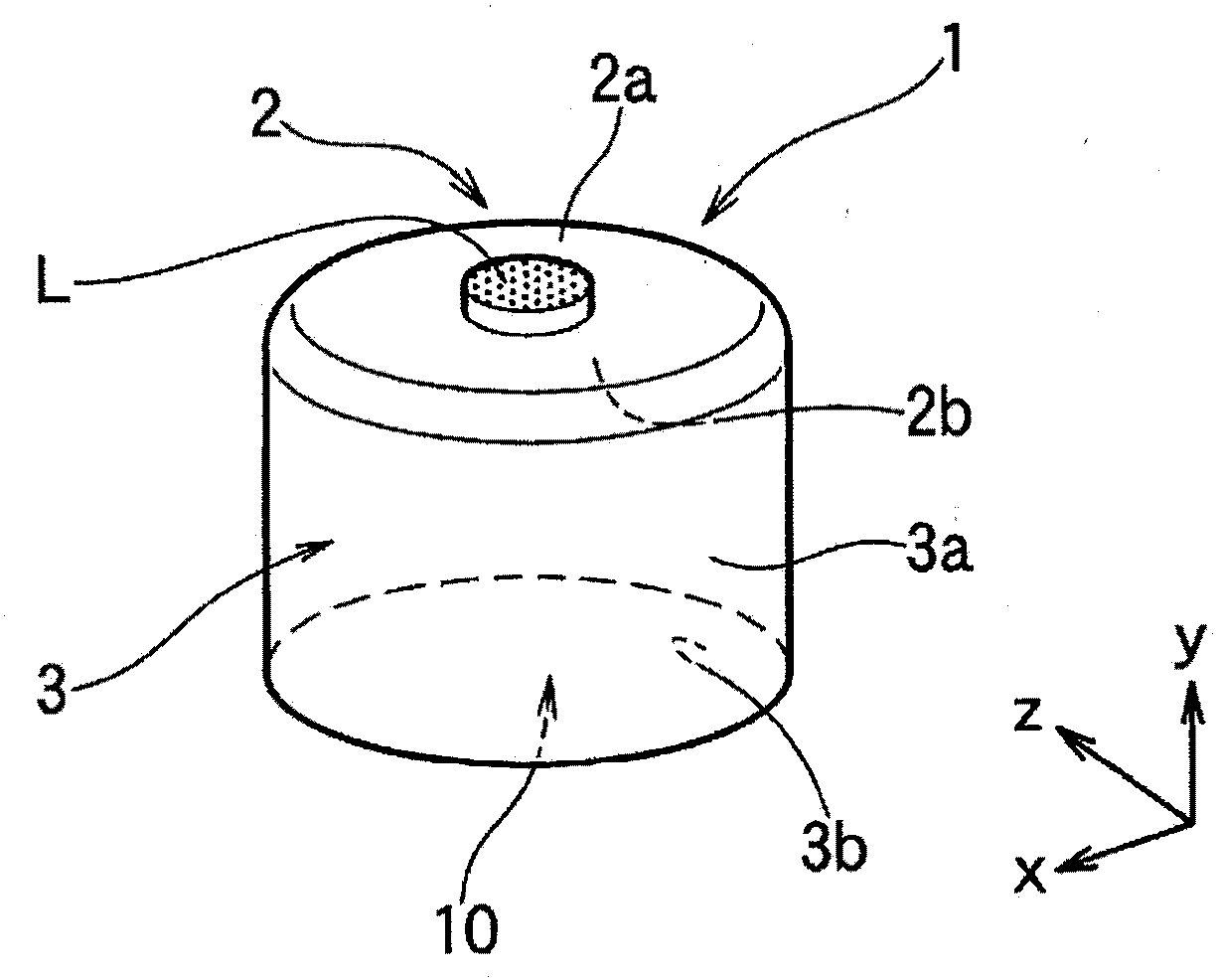
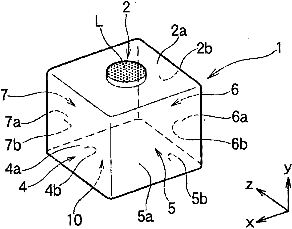
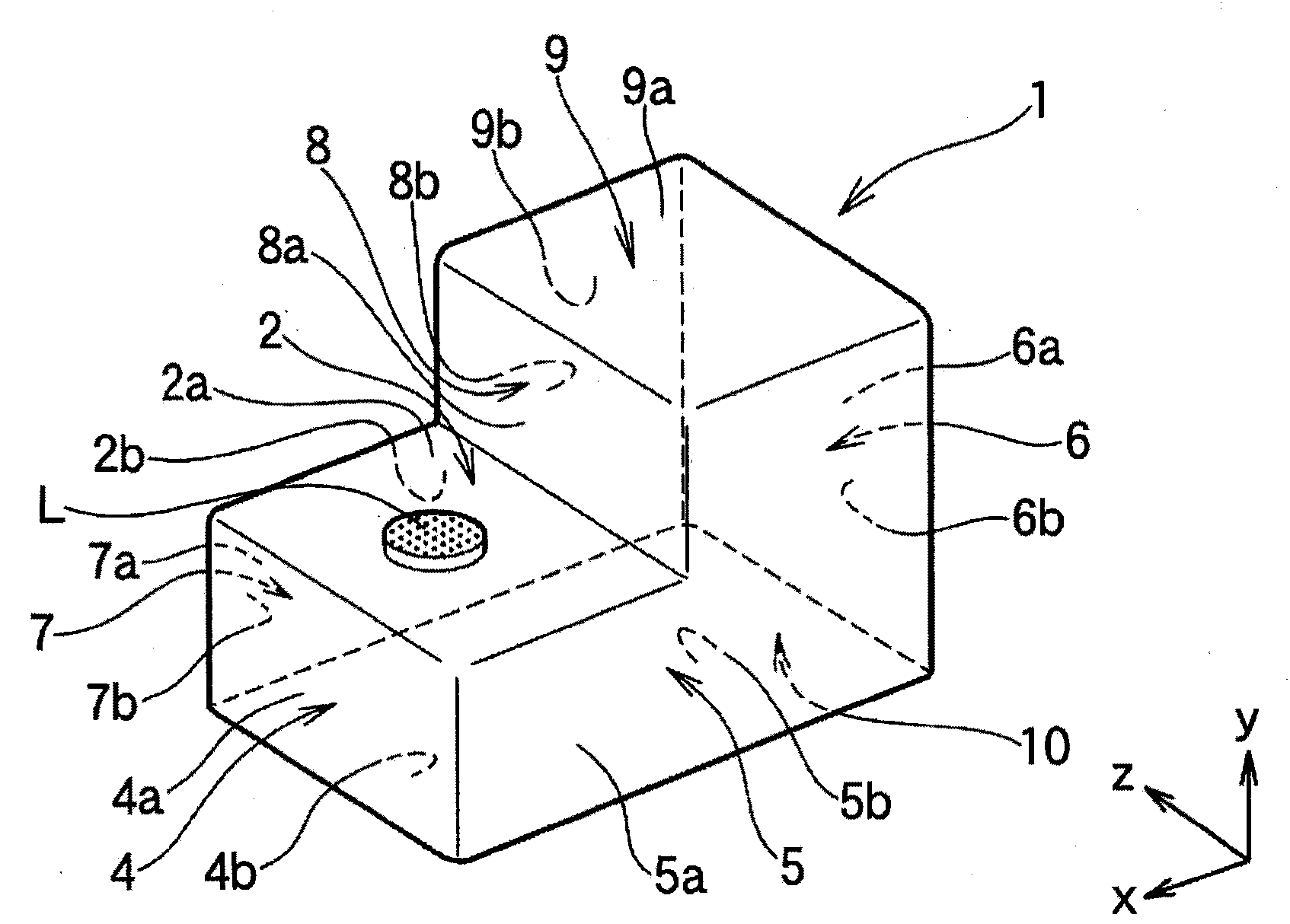
[0088] image 3 The third embodiment of the heat sink for LED lighting according to the present invention is shown. image 3 The heat sink 1 for LED lighting shown is with figure 2 Similarly, a thin metal plate 1 having a constant plate thickness such as aluminum is integrally formed, and figure 2 In that way, the whole has a hollow square tube shape (square tube cup shape). figure 2 The heat sink 1 for LED lighting of the present invention is similar to the above-mentioned point in that the LED element mounting surface 2 and the heat dissipation side surface 3 are integrally formed from a thin metal plate by drawing processing. figure 1 , 2 The situation is the same.

[0089] The image 3 The heat sink 1 for LED lighting has an LED element mounting surface 2 and four flat heat-dissipating side surfaces 4, 5, 6, 7, and becomes the Y-direction (up and down) of the drawing which is a section higher than the LED element mounting surface 2. In the direction), the stepped surface 8 ...

no. 4 approach

[0098] Figure 4 The fourth embodiment of the heat sink for LED lighting according to the present invention is shown. Figure 4 The heat sink 1 for LED lighting shown is the same as figure 2 The same overall shape but no figure 2 Like the opening 10 on the bottom side, the heat dissipating side surface 6 in the middle has an opening (space part) 11 where the heat dissipating side surface does not actually exist and the internal space of the cylindrical body is open to the outside.

[0099] The opening 11 is provided in a range that does not hinder the rigidity of the heat sink 1, and in cooperation with the opening 10 on the bottom side, it can have a larger area than the heat dissipation side area of ​​the heat sink 1. Therefore, the convection function of the air in the internal space and the outside air through the openings 10 and 11 inside and outside the heat sink 1 is improved. As a result, and figure 2 Compared with the case of, although the area of ​​the heat dissipatio...


PUM

PropertyMeasurementUnit
Plate thicknessaaaaaaaaaa

Abstract

The present invention relates to an LED lighting heat sink which is capable of being manufactured from an aluminum plate by a relatively simple processing method, and efficiently performs heat radiation even when applied to and installed in a closed space. The LED lighting heat sink according to the present invention is an LED lighting heat sink (1) where an LED element mounting surface (2) and a radiation side surface (3) are formed integrally or continuously on one sheet metal by drawing. The heat sink of the present invention comprises radiation surfaces in a continuous manner, which are formed on a cylindrical body to face any three-dimensional direction.

Description

Technical field [0001] The present invention relates to a heat sink for LED lighting for dissipating heat generated during light emission of LED lighting using light-emitting diode (LED) elements (including a structure in which multiple elements are mounted on a substrate, etc.) as a light-emitting source to the surrounding space sheet. Background technique [0002] Lighting using light-emitting diode (LED) elements as the light-emitting source has gradually penetrated the market due to its low power consumption and long life. This LED lamp has general bulb type LED bulbs developed with the goal of replacing existing bulbs such as incandescent lamps and fluorescent lamps, automotive LED lighting such as headlights of motor vehicles, and buried lighting in buildings and other fields. Wait. Among them, in-vehicle LED lighting (vehicle lamps, vehicle headlights) that has attracted particular attention in recent years has begun to replace LED elements. In addition, with the applic...

Claims


Application Information

Patent Timeline
IPC IPC(8): F21V29/00F21Y101/02
CPCF21V29/70F21Y2115/10F28D2021/0029F21V29/00
Inventor 小西晴之
Owner KOBE STEEL LTD
Why Eureka
Try Eureka