Connection method between braided shield layer of shield wire and drain wire, and connection structure of same

一种编织屏蔽层、连接方法的技术,应用在编织线导体、永久变形起作用的连接、连接等方向,能够解决增大未被屏蔽保护的部分、屏蔽性能降低等问题,达到实现连接、可靠连接的效果

Active Publication Date: 2014-07-09
YAZAKI CORP
View PDF6 Cites 17 Cited by
  • Summary
  • Abstract
  • Description
  • Claims
  • Application Information

AI Technical Summary

Problems solved by technology

However, according to this technique, the portion not protected by shielding is enlarged
As a result, there is a problem of reduced shielding performance

Method used


Image

  • Connection method between braided shield layer of shield wire and drain wire, and connection structure of same
  • Connection method between braided shield layer of shield wire and drain wire, and connection structure of same
  • Connection method between braided shield layer of shield wire and drain wire, and connection structure of same

Examples


Embodiment Construction

[0046] A connection method between the braided shielding layer of the shielded wire and the drain wire according to the present invention will be described with reference to the drawings.

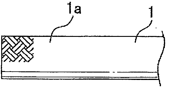
[0047] Figure 1A The vicinity of the end portion of the braided shield layer 1 a of the shielded wire 1 to be connected to the drain wire 3 is schematically shown.

[0048] In this embodiment, the braided shielding layer 1a provided as the outermost layer of the shielded wire 1 is formed by braiding a plurality of wire bundles, each of which is composed of a plurality (eighty in this embodiment) of slightly The single wire of the drain wire described later is formed of a thin conductive single wire (in this embodiment, the outer diameter is 0.24 mm, made of metal-plated fiber).

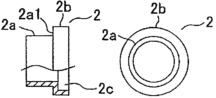
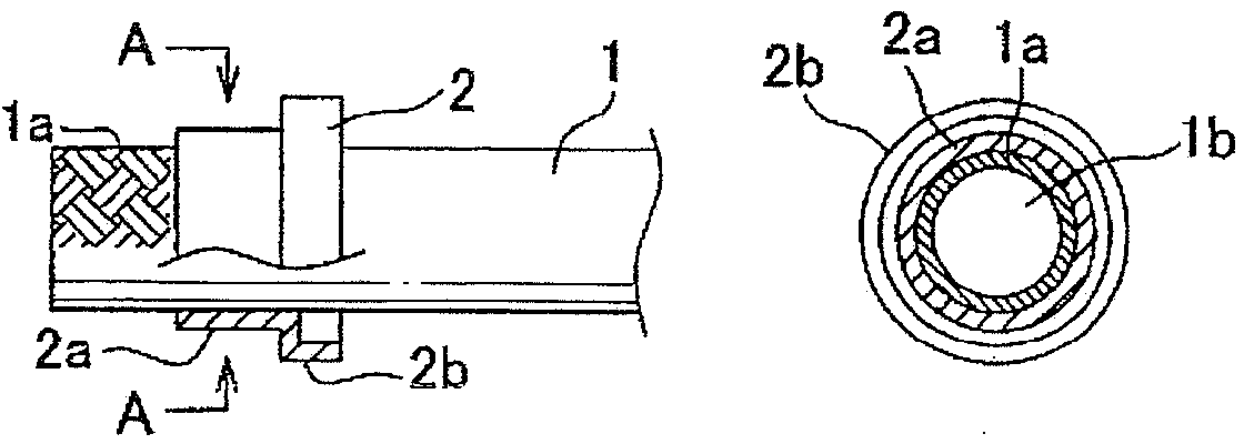
[0049] Such as Figure 1B As schematically shown in the side view and front view of , the shielding terminal 2 is inserted from the end of the shielding wire 1 to the shielding wire 1 ( Figure 1C A schematic s...


PUM


Abstract

To provide a connection method between a braided shield layer of a shield wire and a drain wire, and a connection structure of the same enabling an easy and reliable connection, using no skilled operation such as soldering, and without an increase of non-shield area which is a problem when the braided shield layer is pulled out and a ground terminal is directly crimped onto the braided shield layer. A connection method between a braided shield layer of a shield wire and a drain wire sequentially including the steps of: a shield terminal insertion step; a shield layer folding and overlapping step; a drain wire overlapping step; a shield ring inserting step; and a crimping step.

Description

technical field [0001] The present invention relates to a connection method between a braided shielding layer of a shielded wire and a drain wire for ground connection, the shielded wire being used for connection with an electrical component such as a motor used in an electric vehicle or the like. Background technique [0002] A shielded wire provided with a braided shielding layer each composed of a plurality of conductors by braiding is used to prevent electromagnetic waves from leaking from a conductor to the outside, or to eliminate the influence of electromagnetic waves from the outside on the conductor. It is formed by multiple wire bundles composed of a single wire. [0003] Usually, in these shielded wires, the braided shield is electrically connected to the ground for shielding effect. For this purpose, if image 3 As shown, the ground wire, that is, the drain wire 3 and the braided shielding layer 1a are electrically connected to each other. exist image 3 In the...

Claims


Application Information

Patent Timeline
Patent Type & Authority Applications(China)
IPC IPC(8): H01R4/20H01R4/66H01R9/05H01R43/048
CPCH01R43/048H01B5/12H01R4/20H01R4/66H01R9/0512H01R9/0518H05K9/0088H05K9/0098Y10T29/49199
Inventor 花崎恒
Owner YAZAKI CORP
Why Eureka
Try Eureka