Portable dental therapeutic apparatus

A therapeutic instrument and portable technology, which is applied in the field of portable dental therapeutic instruments, can solve the problems of inability to carry, few operating functions, and high price, and achieve the effect of reducing muscle fatigue and reducing wire confusion and tripping people

Active Publication Date: 2014-07-16
钱能
View PDF7 Cites 11 Cited by
  • Summary
  • Abstract
  • Description
  • Claims
  • Application Information

AI Technical Summary

Problems solved by technology

[0004]The first type is the dental treatment instrument that we usually see in the stomatology department of the hospital. It is not portable, and the equipment is complex and complex, so the price is very expensive. For example, it is difficult for African countries in the third world to afford the purchase of such equipment to help treat local patients. At the same time, there is not enough energy to maintain the operation of the machine. Market demand is also going downhill
In actual use and operation, the other side of the saliva suction device, which is farther away from other appliances, is not easy to pick up and operate. The pedal operator is bulky and difficult to move to a comfortable and effective position. The hanging structure is easy to produce pipes connecting tools. When the dentist puts back the tool without looking at it and prepares to take the adjacent tool, it will affect the workflow. The distance between the two tools is very close, and there is no independent separation structure, so it is easy to take two tools at the same time. , you may accidentally press the control key on the tool, resulting in a messy spraying situation. The drooping structure is inconvenient to take and put back the tool. Stumbling people, the position of the tray is not easy to replace the...

Method used


Image

  • Portable dental therapeutic apparatus
  • Portable dental therapeutic apparatus
  • Portable dental therapeutic apparatus

Examples


Embodiment Construction

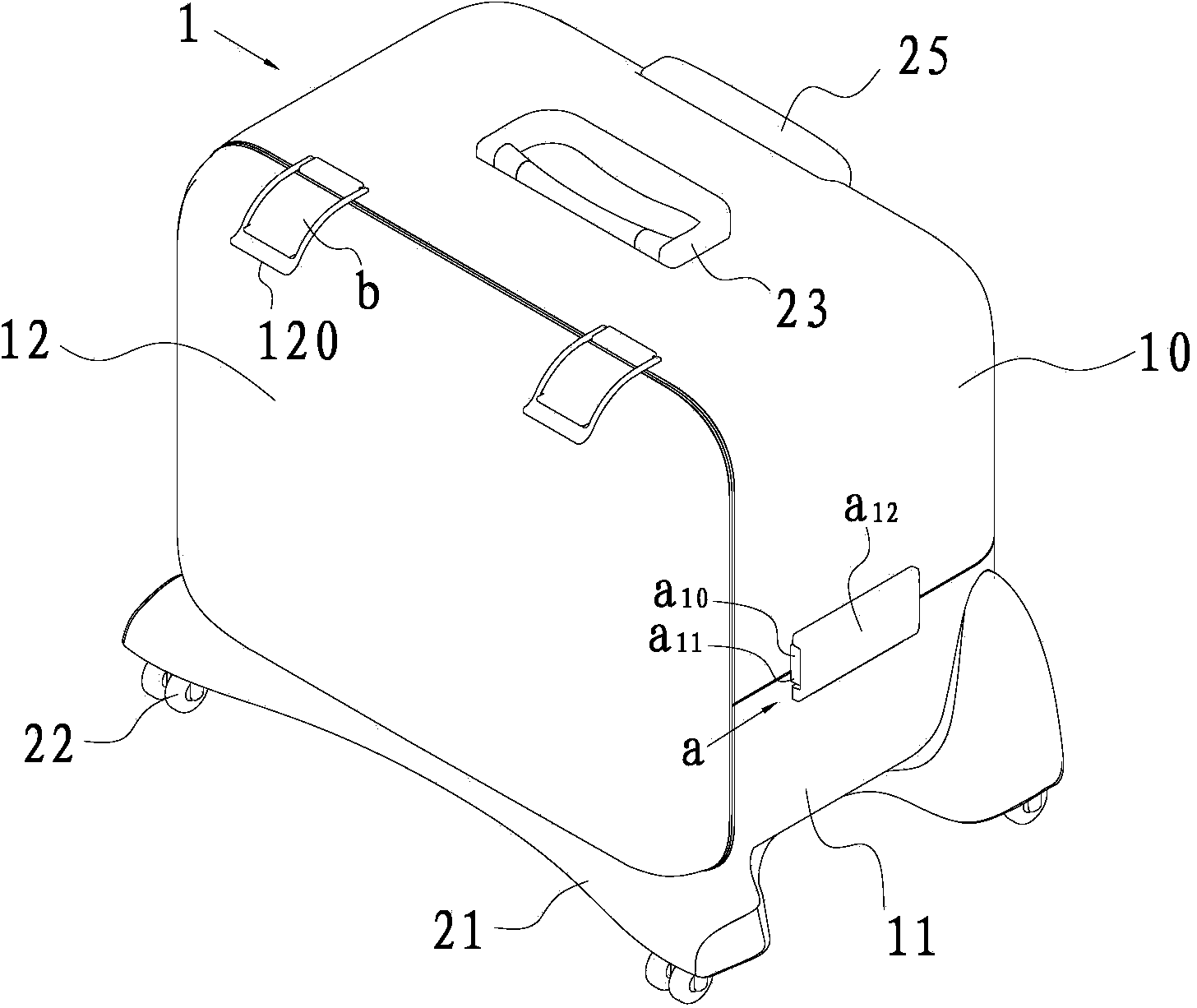
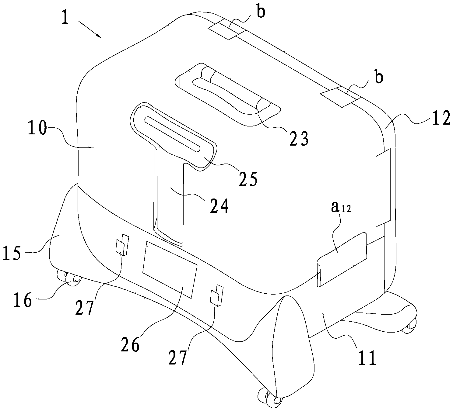
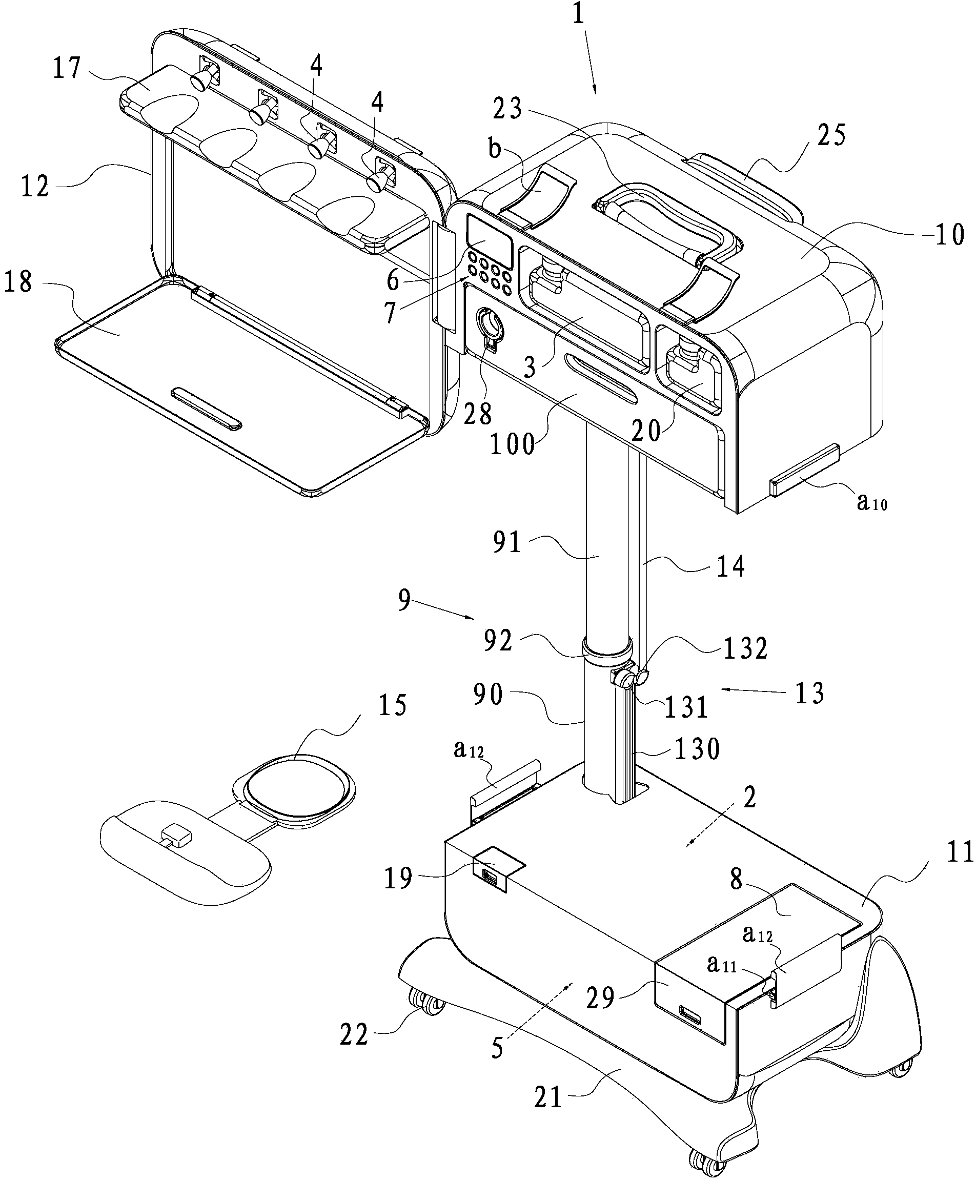
[0037] Such as Figure 1 to Figure 8 As shown, the portable dental treatment instrument of this embodiment includes a casing 1, an air compressor 2, a water tank 3 communicated with the air compressor 2, a joint 4, a treatment tool connected to the joint 4, and a The saliva in the saliva is pumped to the electromagnetic pump 5 in the saliva collection bag, has a display screen 6 and regulates the panel control system 7 and the pipeline system of the amount of sprayed air and water from the treatment tool, especially, the casing 1 includes Upper box body 10 and lower box body 11, are positioned at upper box body 10 and lower box body 11 side and rotate and can buckle and be arranged on the flip cover 12 that is arranged on the side of upper box body 10, dental treatment instrument also includes battery 8, is used for controlling The lock catch a that separates between the upper box body 10 and the lower box body 11, the lifting mechanism 9 that is arranged between the upper b...


PUM


Abstract

The invention relates to a portable dental therapeutic apparatus which comprises a box body, an air compressor, a water tank, a connector, a therapeutic tool, an electromagnetic pump, a panel control system, a pipeline system, a storage battery, a fastener, an elevating mechanism, a guide roller system and a wireless pedal control unit, wherein the panel control system is provided with a display screen and used for adjusting the quantities of air and water sprayed from the therapeutic tool; the box body comprises an upper box body, a lower box body and a flip cover, which is positioned on one side of the upper box body and the lower box body, can rotate and can be buckled on the side surface of the upper box body; the fastener is used for controlling the closing and separation of the upper box body and the lower box body; the elevating mechanism is arranged between the upper box body and the lower box body; the guide roller system can release or tighten a connecting sleeve along with the rise or fall of the elevating mechanism; the wireless pedal control unit is used for controlling the working power of the therapeutic tool; and the pipeline system is positioned in the connecting sleeve. The dental therapeutic apparatus can be normally used in any location, can effectively reduce the phenomenon of stumble of people, and has the advantages of simple and compact structure and smaller occupied space.

Description

technical field [0001] The invention belongs to the field of medical equipment, in particular to a portable dental treatment instrument. Background technique [0002] As we all know, the dental treatment instrument is mainly used for: oral care (for example: ablation of tartar, root grinding, sealing); oral maintenance (for example: tooth filling, restoration); endodontics: (for example: root canal treatment); denture prosthesis Maintenance, repairs, implants, replacements; and periodontitis treatment. [0003] At present, there are two types of dental treatment instruments (equipment) on the market: [0004] The first is the dental treatment instrument that we usually see in the stomatology department of the hospital. Its disadvantages: the equipment occupies a large area, and it needs to occupy a fixed indoor area, and it cannot be carried. African countries in the third world can hardly afford to purchase such devices to help treat local patients. At the same time, ther...

Claims


Application Information

Patent Timeline
IPC IPC(8): A61C19/06
CPCA61C19/02A61C19/06
Inventor 钱能
Owner 钱能
Why Eureka
Try Eureka