
Chemical instrument trolley

A chemical instrument and stage technology, applied in the field of chemical instrument carts, can solve the problems of test tube breakage, low stage, collision, etc., and achieve the effect of being difficult to move.

Inactive Publication Date: 2014-07-16
SUZHOU BOXUN INSTR
View PDF7 Cites 2 Cited by
  • Summary
  • Abstract
  • Description
  • Claims
  • Application Information

AI Technical Summary

Problems solved by technology

[0003] In chemical experiments, various instruments are often used. The instrument cart can use more instruments at one time, thereby reducing the time and manpower required for transporting instruments. However, the structure of the existing instrument cart is unstable, and the periphery of the stage There is no hoarding board or the hoarding board is too low, and there is no anti-skid facility on the stage surface. Therefore, the transported instrument cannot be placed stably, and it is prone to movement, collision, overturning, falling, etc., and the existing instrument cart does not have Set up equipment for transporting a large number of test tubes. When transporting various test tubes, it is necessary to place different types of test tube racks or place the test tubes in a container of the test tube rack by mistake, which will easily cause damage to the test tubes. At the same time, it is difficult to ensure the quality of the test tubes. In addition, when transporting chemical instruments that have been washed, the existing instrument carrier is not equipped with a drainage device, so it cannot be used as a carrier for air-drying instruments, nor can it keep the carrier dry and clean

Method used


Image

  • Chemical instrument trolley

Examples


Embodiment Construction

[0017] The present invention is described below in conjunction with accompanying drawing.

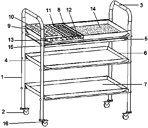
[0018] refer to figure 1 As shown, a chemical instrument cart includes a frame body 1 and a pulley 2, the frame body 1 is fixedly connected with the pulley 2, and the frame body 1 includes a handrail 3, a stage 4 and a stretching water receiving basin 5 , the loading table 4 is provided with more than two layers, the surrounding board 6 is arranged around the loading table 4, the table top 7 of the loading table 4 is a corrosion-resistant non-slip table top, and the loading table 4 on the top A clapboard 8 is arranged on it, and a detachable test tube rack 9 is arranged on one side of the clapboard 8, and the detachable test tube rack 9 is set in steps, the detachable test tube rack 9 is divided into three layers, and the detachable test tube rack 9 is divided into three layers. Type test tube rack frame surface 10 is provided with test tube round holes 11, and described test tube roun...


PUM


Abstract

The invention discloses a chemical instrument trolley. The chemical instrument trolley comprises a frame body and pulleys fixedly connected with the frame body, wherein the frame body comprises handrails, objective tables and stretching type water receiving basins, surrounding plates are arranged around the objective tables, table surfaces of the objective tables are corrosion-resistant anti-skidding table surfaces, a partition board is arranged on the objective table at the top of the frame body, a detachable test tube frame is arranged on one side of the partition board, round test tube holes are formed in the surface of the detachable test tube frame, an inner layer is arranged in the detachable test tube frame, round fixed holes corresponding to the round test tube holes in the surface of the detachable test tube frame are formed in the inner layer, small draining round holes are formed in the table surface of the objective table at the top of the frame body, and the corresponding stretching type water receiving basin is arranged at the bottom of the objective table at the top of the frame body; the pulleys are universal wheels. The chemical instrument trolley has the beneficial effects that the structure is stable, instruments are unlikely to move, collide with one another, turn over and fall when the chemical instrument trolley is pushed, and the chemical instrument trolley can be used for safely conveying a great number of test tubes of different types and is provided with a draining device.

Description

[0001] technical field [0002] The invention relates to a chemical instrument cart. Background technique [0003] In chemical experiments, various instruments are often used. The instrument cart can use more instruments at one time, thereby reducing the time and manpower required for transporting instruments. However, the structure of the existing instrument cart is unstable, and the periphery of the stage There is no hoarding board or the hoarding board is too low, and there is no anti-skid facility on the stage surface. Therefore, the transported instrument cannot be placed stably, and it is prone to movement, collision, overturning, falling, etc., and the existing instrument cart does not have Set up equipment for transporting a large number of test tubes. When transporting various test tubes, it is necessary to place different types of test tube racks or place the test tubes in a container of the test tube rack by mistake, which will easily cause damage to the test tube...

Claims


Application Information

Patent Timeline
Patent Type & Authority Applications(China)
IPC IPC(8): B01L9/00B01L9/06
Inventor 程鸿林姚海波
Owner SUZHOU BOXUN INSTR
Learn More