Differential pressure forming method for local large-deformation hollow pieces

A technology of large deformation and hollow parts, which is applied in the differential pressure forming of hollow parts and the differential pressure forming of hollow parts with local large deformation, which can solve the problems that the balance punch is difficult to function, the local expansion rate and the complex mold structure cannot be solved. , to achieve the effect of convenient feeding and final forming, simple structure and increasing bulging limit

Inactive Publication Date: 2014-07-16
NANJING UNIV OF AERONAUTICS & ASTRONAUTICS
View PDF6 Cites 16 Cited by
  • Summary
  • Abstract
  • Description
  • Claims
  • Application Information

AI Technical Summary

Problems solved by technology

[0006] The above method can alleviate the cracking or excessive thinning of the tube blank in the local large deformation to a certain extent, but it cannot solve the forming problem of excessive local expansion rate (the local expansion rate is more than twice the material elongation rate)
Although the structural optimization of the formed part can improve the stress state of the tube blank during the bulging process, it has a good effect, but when the local large deformation is not concentrated in one place (such as multi-pass), but continuously distributed in the circumferential direction, The balanced punch will be difficult to function, and the mold structure will be extremely complicated, which will increase the manufacturing cost dramatically

Method used


Image

  • Differential pressure forming method for local large-deformation hollow pieces
  • Differential pressure forming method for local large-deformation hollow pieces
  • Differential pressure forming method for local large-deformation hollow pieces

Examples


Embodiment 1

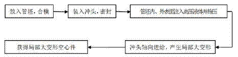
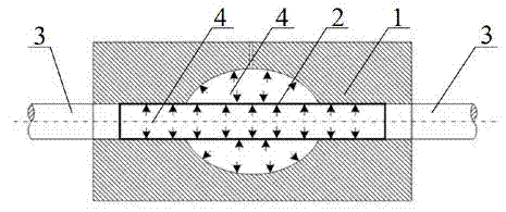
[0025] In the first step, the surface of the 304 stainless steel tube blank 2 with a diameter of 50mm, a length of 300mm and a wall thickness of 2mm is cleaned and put into the convex mold 1, and the upper and lower molds are closed;

[0026] In the second step, the punch 3 is loaded into the tube blank and sealed;

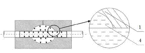
[0027] The third step is to inject hydraulic oil 4 into the inside of the tube blank 2 and the outer surface of the tube blank (that is, the inside of the mold 1) at the same time, and quickly increase the hydraulic pressure inside the tube blank 2 to 45MPa, and the hydraulic pressure outside the tube blank 2 to 7MPa , and then slowly increase the hydraulic pressure inside and outside the tube blank 2 at the same time, control the hydraulic pressure inside the tube blank 2 to basically maintain at 50MPa during the working stage, and maintain the hydraulic pressure outside the tube blank 2 at 10MPa during the working stage, control the inside of the tube blank, the ...

Embodiment 2

[0031] The first step is to clean the surface of 20 steel tube blanks with a diameter of 40 mm, a length of 500 mm, and a wall thickness of 2 mm, and then put them into a stepped mold, and the upper and lower molds are closed;

[0032] The second step is to put the punch into the tube blank and seal it;

[0033] The third step is to inject high-pressure liquid into the inside of the tube blank and the outer surface of the tube blank (that is, the inside of the mold) at the same time, quickly increase the hydraulic pressure inside the tube blank to 40MPa, and increase the hydraulic pressure outside the tube blank to 7MPa, and then increase slowly The hydraulic pressure inside and outside the tube blank is controlled to maintain the hydraulic pressure inside the tube blank at 45MPa during the working stage, the hydraulic pressure outside the tube blank is basically maintained at 10MPa during the working stage, and the pressure difference between the inside and outside of the tube...

Embodiment 3

[0037] The first step is to clean the surface of the 304 stainless steel tube blank with a diameter of 30mm, a length of 400mm and a wall thickness of 2mm and put it into the three-way mold, and the upper and lower molds are closed;

[0038] The second step is to put the punch into the tube blank and seal it;

[0039] The third step is to inject water into the tube blank, inject hydraulic oil into the outer surface of the tube blank (that is, inside the mold), quickly increase the hydraulic pressure inside the tube blank to 60 MPa, and increase the hydraulic pressure outside the tube blank to 3 MPa, and then Slowly increase the hydraulic pressure inside and outside the tube blank, control the hydraulic pressure inside the tube blank to basically maintain at 65MPa during the working stage, maintain the hydraulic pressure outside the tube blank at 5MPa during the working stage, and control the pressure difference between the inside and outside of the tube blank to 60MPa;

[0040...


PUM


Abstract

The invention discloses a differential pressure forming method for local large-deformation hollow pieces and belongs to the technical field of manufacturing of metal hollow members. The differential pressure forming method includes steps of firstly placing a pipe billet into a rear die, loading a punch into the pipe billet and sealing; injecting high-pressure liquid to the inner and outer surfaces of the pipe billet at the same time, keeping pressure in the pipe billet larger than the pressure of the outer surface of the pipe billet and forming controllable pressure difference; pushing the punch to axially feed to realize material supplement by the aid of a hydraulic cylinder, and enabling the pipe billet to generate local large deformation under the action of inside and outside hydraulic differential pressure; finally, discharging the high-pressure liquid and obtaining a local large-deformation hollow piece. By controlling inside and outside pressure difference of the pipe billet, stress state during local expansion of the pipe billet can be improved, expansion can be sufficiently realized and expansion limit is increased. Hydraulic oil is injected onto the outer surface of the pipe billet, lubricating between the outer surface of the pipe billet and a form cavity of the die is evidently improved, friction is reduced, and axial supplement and final forming are facilitated.

Description

technical field [0001] The invention relates to a differential pressure forming method of a hollow part, in particular to a differential pressure forming method of a partially deformed hollow part, belonging to the technical field of metal hollow member manufacturing. Background technique [0002] Hydraulic bulging technology is a common method for manufacturing hollow structural parts due to its high forming efficiency. Through hydraulic bulging technology, hollow structural parts with complex cross-sections can be obtained, which are widely used in aerospace, nuclear power, petrochemical and other engineering fields. [0003] With the rapid development of internal high pressure forming technology, there are more and more hollow structural parts with local large deformation characteristics. Large local deformation means that the local section expansion rate far exceeds the elongation rate of the material. In the hydraulic bulging process, if the parameters of the bulging ...

Claims


Application Information

Patent Timeline
Patent Type & Authority Applications(China)
IPC IPC(8): B21D26/033
Inventor 郭训忠陶杰徐翌伟范敏郁
Owner NANJING UNIV OF AERONAUTICS & ASTRONAUTICS
Why Eureka
Try Eureka