Drilling device for wheel insert

A drilling device and insert technology, applied in positioning devices, boring/drilling, drilling/drilling equipment, etc., can solve problems such as drilling, and achieve high processing efficiency, advanced technology and high positioning accuracy. Effect

Active Publication Date: 2014-07-16
CITIC DICASTAL
5 Cites 18 Cited by

AI-Extracted Technical Summary

Problems solved by technology

[0002] With the continuous improvement of the appearance of the wheels, the wheels with different colored plastic decorations on the spokes are ...

Abstract

The invention discloses a drilling device for a wheel insert. The drilling device is composed of a rack, cylinders, a transverse sliding table, a vertical sliding table, a servo motor, a mandrel and the like. A wheel is positioned preliminarily through a sensor, the wheel is positioned in the axial direction through four V-type idler wheels which are driven by the clamping cylinder through a gear rack and a gear, and the wheel is positioned in the radial direction through the mandrel which is driven by the lifting cylinder through a lifting post. The wheel is driven by the servo motor III to rotate and stops rotating after the sensor detects the position of an air valve hole of the wheel, and a drill bit is positioned through the transverse sliding table and the vertical sliding table. Insert holes in a rim can be machined on line in the using process of the drilling device, machining efficiency and positioning accuracy are high, and meanwhile the drilling device has the advantages of being advanced in technology, high in automation degree and safe and reliable in performance.

Application Domain

Technology Topic

Image

  • Drilling device for wheel insert
  • Drilling device for wheel insert
  • Drilling device for wheel insert

Examples

  • Experimental program(1)

Example Embodiment

[0014] The details and working conditions of the specific device proposed according to the present invention will be described below in conjunction with the accompanying drawings.
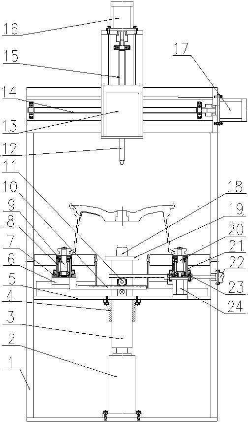
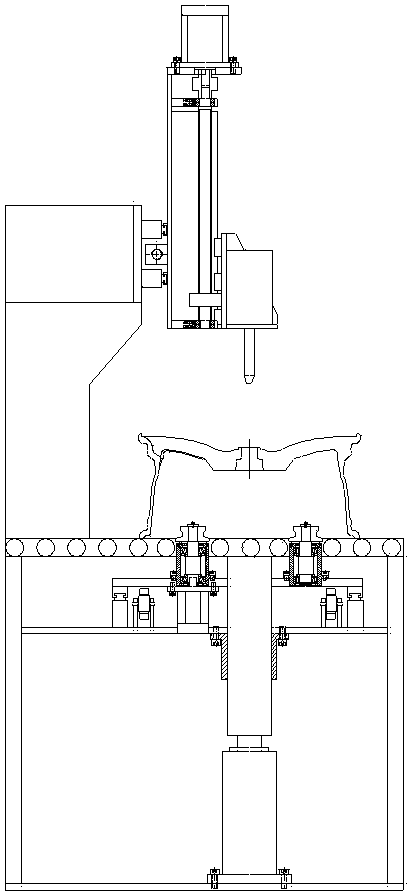
[0015] The device consists of frame 1, lifting cylinder 2, lifting column 3, guide sleeve 4, base plate 5, guide rail 6, left slide plate 7, left bearing seat 8, left shaft 9, rack 10, gear 11, drill bit 12, power head 13. Horizontal sliding table 14, vertical sliding table 15, servo motor Ⅰ16, servo motor Ⅱ17, mandrel 18, tray 19, right shaft 20, right bearing seat 21, clamping cylinder 22, right sliding plate 23 and servo motor Ⅲ24 The lifting cylinder 2 is fixed on the bottom of the frame 1, the output end of the lifting cylinder 2 is connected to the bottom of the lifting column 3; the tray 19 is fixed on the upper end of the lifting column 3, and the mandrel 18 matched with the center hole of the wheel is fixed on the top of the tray 19 The guide sleeve 4 matched with the lifting column 3 is installed below the base plate 5; the lower end is fixed with a rack 10, and the left slide plate 7 with a left bearing seat 8 is fixed at the upper end through the guide rail 6 and fixed above the base plate 5; the upper end is fixed with a V-shaped roller. Two left shafts 9 are fixed in two left bearing blocks 8 by bearings.
[0016] The right end is fixed with the horizontal sliding table 14 of the servo motor II 17, which is fixed on the top of the frame 1; the upper side is fixed with the servo motor I 16, and the lower part is fixed with the vertical sliding table 15 of the power head 13, which is installed on the horizontal sliding table 14, and the drill bit 12 is installed At the output end of the power head 13.
[0017] The right bearing seat 21 is fixed on the top, and the right slide plate 23 of the servo motor III 24 is fixed on the bottom, which is fixed above the bottom plate 5 through the guide rail 6; two right shafts 20 with V-shaped rollers are fixed on the upper end, and are fixed on the two right bearing seats through bearings In 21; the output rod of the clamping cylinder 22 installed on the side of the frame 1 is connected with the right slide plate 23, and the synchronous clamping movement of the left shaft 9 and the right shaft 20 to the wheels is realized by the rack 10 and the gear 11.
[0018] The clamping cylinder 22 enables the four V-shaped rollers to realize the axial positioning of the wheels through the rack 10 and the gear 11, and the mandrel 18 realizes the radial positioning of the wheels.
[0019] During the working process, the sensor makes the initial positioning of the wheel, the clamping cylinder 22 makes the four V-shaped rollers realize the axial positioning of the wheel through the rack 10 and the gear 11, and the lifting cylinder 2 makes the mandrel 18 realize the alignment through the lifting column 3 Radial positioning of the wheels. Servo motor III 24 drives the wheel to rotate, and the sensor stops after detecting the position of the valve hole of the wheel, and the positioning of the drill bit is realized through the horizontal slide 14 and the vertical slide 15.

PUM

no PUM

Description & Claims & Application Information

We can also present the details of the Description, Claims and Application information to help users get a comprehensive understanding of the technical details of the patent, such as background art, summary of invention, brief description of drawings, description of embodiments, and other original content. On the other hand, users can also determine the specific scope of protection of the technology through the list of claims; as well as understand the changes in the life cycle of the technology with the presentation of the patent timeline. Login to view more.

Similar technology patents

Rapid behavior identification method and system

ActiveCN105095866AImprove processing efficiencyGuaranteed orderCharacter and pattern recognitionOffline learningSlide window
Owner:CHONGQING UNIV OF POSTS & TELECOMM

Classification and recommendation of technical efficacy words

  • Improve processing efficiency
  • High positioning accuracy

Acid tank sealing treatment system

Owner:YANTAI JEREH PETROLEUM EQUIP & TECH
Why Eureka
Try Eureka