Rotary-table center positioning method for spindle-driving-five-shafts machining center

A five-axis machining center and rotary table technology, applied in metal processing equipment, metal processing machinery parts, manufacturing tools, etc.

Inactive Publication Date: 2014-07-16
NORTHWESTERN POLYTECHNICAL UNIV
View PDF6 Cites 14 Cited by
  • Summary
  • Abstract
  • Description
  • Claims
  • Application Information

AI Technical Summary

Problems solved by technology

This method can effectively solve the problem of the center positioning of the worktable in the end milling state of the spindle swinging five-axis machining center

Method used


Image

  • Rotary-table center positioning method for spindle-driving-five-shafts machining center
  • Rotary-table center positioning method for spindle-driving-five-shafts machining center
  • Rotary-table center positioning method for spindle-driving-five-shafts machining center

Examples


Embodiment Construction

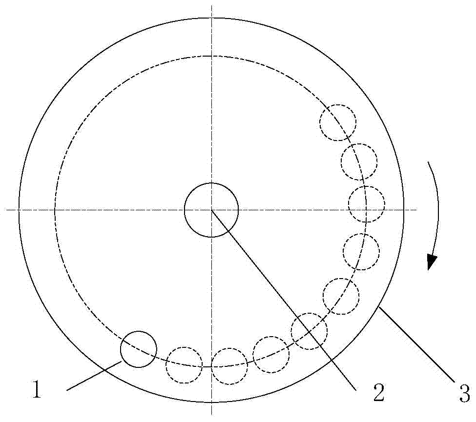
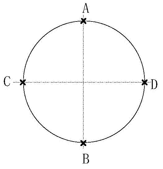
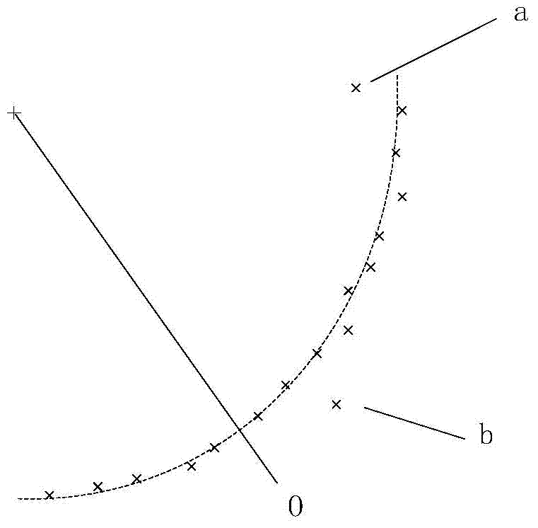
[0040] The following examples refer to Figure 1-3 .

[0041] Step 1: place and fix a ring gauge 1 on the rotary table 3 of the spindle swing five-axis machining center;

[0042]Requirement a: The inner hole diameter d of the ring gauge 1 (20mm≤d≤50mm) is convenient for the machine tool spindle to find the center of the ring gauge 1, the parallelism of the upper and lower end faces of the ring gauge 1≤0.005, and the perpendicularity between the end face of the ring gauge 1 and the central axis≤ 0.005, ring gauge 1 central hole roundness ≤ 0.005. Fix the ring 1 gauge at a position as far away from the center 2 of the rotary table as possible, and in the end milling state, the center of the ring gauge 1 that the spindle can reach;

[0043] Requirement b: The ring gauge 1 is installed horizontally on the workbench 3, and the parallelism between the end face and the workbench 3 is ≤0.005.

[0044] Step 2: The spindle swings. The five-axis machining center is in the end milling ...


PUM


Abstract

The invention discloses a rotary-table center positioning method for a spindle-driving-five-shafts machining center, aiming to solve the technical problem that an existing rotary-table center positioning method for the spindle-driving-five-shafts is poor in implementation. The technical scheme is that center coordinates of a ring gauge under different rotary angles of a rotary table are acquired multiple times and are matched into a circular curve to acquire the circular center and determine the table center. By the method, the problem about positioning of the table center of the spindle-driving-five-shafts machining center under the end milling condition can be effectively solved, the positioning accuracy can reach 0.001mm through detection, and requirements of a machine for machining accuracy can be met.

Description

technical field [0001] The invention relates to a method for positioning the center of a rotary table, in particular to a method for positioning the center of a rotary table for a spindle swing five-axis machining center. Background technique [0002] CNC machine tools are widely used in the field of manufacturing. The spindle swing five-axis machining center is a more commonly used five-axis CNC machine tool. The machine tool is equipped with a 360° rotary table and a spindle with a swing range of more than 90°, which is suitable for processing complex parts such as blisks, impellers, and nozzle rings. When the five-axis machine tool is installed and debugged, it is first necessary to find the exact position of the center of the rotary table in the machine tool coordinate system. If there is a deviation from the actual value, the machine tool will not track accurately when the five-axis linkage works, resulting in machining errors of the parts. Affect the machining accura...

Claims


Application Information

Patent Timeline
Patent Type & Authority Applications(China)
IPC IPC(8): B23Q17/00B23Q1/25
CPCB23Q1/525
Inventor 王增强杨艳蔺小军陈悦高源
Owner NORTHWESTERN POLYTECHNICAL UNIV
Why Eureka
Try Eureka