Plunger pump and carbon dioxide injection device for oil field

A carbon dioxide, plunger pump technology, applied in the components, pumps, pump elements, etc. of the pumping device for elastic fluid, to achieve the effect of stable pressure and rapid automatic separation

Active Publication Date: 2014-07-16
CHINA PETROLEUM & CHEM CORP +2
View PDF9 Cites 8 Cited by
  • Summary
  • Abstract
  • Description
  • Claims
  • Application Information

AI Technical Summary

Problems solved by technology

Adopt the structure of top in and bottom out, the gas generated in the pump chamber will automatically rise to the upper part of the liquid inlet chamber due to its light specific gravity, and will be discharged through the exhaust channel. The liquid chamber will not mix with the liquid medium, which is easy to discharge, and the liquid medium in the liquid inlet chamber will not be discharged through the exhaust channel, so that the gas can be discharged quickly; at the same time, the pressure in the liquid inlet chamber is equal to the pressure in the medium storage tank. Therefore, the pressure of the gas discharged from the liquid inlet chamber is greater than the pressure of the gas discharged from the pump chamber, which overcomes the defect that the gas discharged from the pump chamber cannot automatically return to the medium storage tank due to low pressure; the pressure in the liquid inlet chamber is stable, and the vaporized medium will not be caused by Pressure changes into solids, avoiding clogging of exhaust passages

Method used


Image

  • Plunger pump and carbon dioxide injection device for oil field
  • Plunger pump and carbon dioxide injection device for oil field
  • Plunger pump and carbon dioxide injection device for oil field

Examples


Embodiment 1

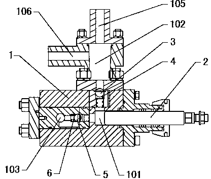
[0035] refer to figure 1The plunger pump includes a pump body 1 and a plunger 2. The pump body 1 is L-shaped. The pump body 1 is respectively provided with a pump chamber 101, a liquid inlet chamber 102 and a liquid discharge chamber 103. The liquid inlet chamber 102 is located in the vertical position of the pump body 1. At the upper end of the straight part, the pump chamber 101 is located in the L-shaped bending part of the pump body 1, the liquid discharge chamber 103 is located in the horizontal part of the pump body 1, the plunger 2 is movably arranged in the pump chamber 101, and the liquid inlet chamber 102 is connected to the pump chamber 101. In the upper part, the liquid discharge chamber 103 communicates with the side of the pump chamber 101, and the upper part of the liquid inlet chamber 102 communicates with the outside of the pump body 1 through the exhaust passage 105. The vaporized medium in the pipeline and the vaporized medium in the pump chamber 101 will aut...

Embodiment 2

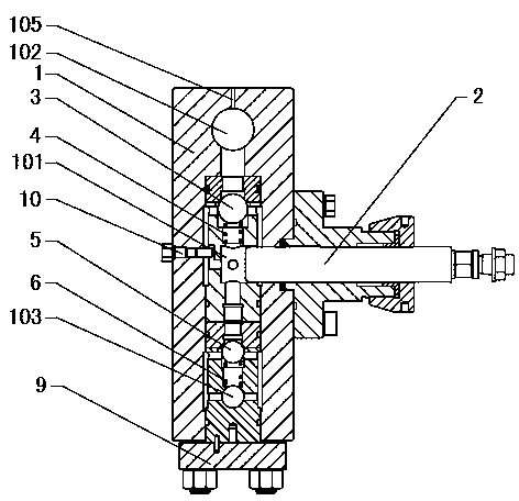
[0041] refer to figure 2 The plunger pump includes a pump body 1 and a plunger 2. The pump body 1 is a straight-through type. The pump body 1 is provided with a liquid inlet chamber 102, a pump chamber 101 and a liquid discharge chamber 103 from top to bottom. The lower end of the pump body 1 is sealed. A flange 9 is fixed, and the plunger 2 is movable in the pump chamber 101. An exhaust passage 105 is provided at the upper end of the pump body 1. The inner end of the exhaust passage 105 communicates with the upper part of the liquid inlet chamber 102, and the outer end of the exhaust passage 105 communicates. Outside the pump body 1, after the medium in the pump chamber 101 vaporizes, the gas has a light specific gravity and rises automatically. It enters the top of the liquid inlet chamber 102 from the pump chamber 101 and is discharged through the exhaust channel 105. The exhaust is smooth and the liquid inlet chamber 102 The pressure in the medium storage tank is equal to...

Embodiment 3

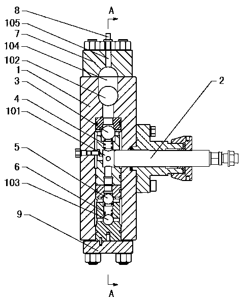
[0043] refer to Figure 3-4 The difference between this embodiment and Embodiment 2 is that a liquid inlet chamber pressure plate 7 is fixed on the upper end of the pump body 1, an air collection chamber 104 is opened between the liquid inlet chamber pressure plate 7 and the pump body 1, and the liquid inlet chamber 102 communicates with the collection chamber. The lower part of the air chamber 104, the exhaust channel 105 is opened on the pressure plate 7 of the liquid inlet chamber, and communicates with the upper part of the gas collection chamber 104, the gas generated in the pump chamber 101 rises into the liquid inlet chamber 102 and continues to rise, and the gas will be concentrated On the upper part of the gas collection chamber 104, the exhaust channel 105 can effectively prevent the liquid medium in the liquid inlet chamber 102 from being discharged with the gas when discharging the gas, realize gas-liquid separation, improve the exhaust performance and the working e...


PUM


Abstract

The invention discloses a plunger pump and a carbon dioxide injection device for an oil field, and belongs to the technical field of plunger pumps. The plunger pump is characterized in that a liquid inlet cavity (102) is formed above a pump cavity (101) and communicated with the upper portion of the pump cavity (101), a liquid outlet cavity (103) is communicated with the lower portion or the lateral portion of the pump cavity (101), the upper portion of the liquid inlet cavity (102) is communicated with the exterior of a pump body (1) through a gas outlet channel (105), gas can automatically rise to the upper portion of the liquid inlet cavity (102), and due to the fact that the pressure of the liquid inlet cavity (102) is low, gas-liquid separation is automatically achieved so that the gas can be conveniently and rapidly discharged out. The invention further provides the carbon dioxide injection device for the oil field, the carbon dioxide injection device comprises a carbon dioxide storage tank (12), a liquid inlet pipe (13) and the plunger pump, the gas outlet channel (105) is communicated with the top of the carbon dioxide storage tank (12) through a backflow pipe (14), the two ends of the liquid inlet pipe (13) are communicated with the bottom of the carbon dioxide storage tank (12) and the liquid inlet cavity (102) respectively, and gas-state carbon dioxide is recycled into the carbon dioxide storage tank (12).

Description

technical field [0001] A plunger pump and a carbon dioxide injection device for oil fields belong to the technical field of plunger pumps, and also relate to a carbon dioxide injection device for oil fields. Background technique [0002] When the plunger pump is used to transport easily vaporized liquids such as carbon dioxide, the volume of the pump cavity becomes larger when the plunger withdraws, the pressure in the pump cavity decreases rapidly, the liquid carbon dioxide in the pump cavity is easy to vaporize, and the gaseous carbon dioxide in the pump cavity will be seriously reduced. The working efficiency of the plunger pump, Chinese Patent No. 98204169.1 discloses a liquid carbon dioxide injection device. A discharge valve connected to the pump chamber is provided on the pump body to discharge the gas in the pump chamber. The applicant is in the production test During the process, it was found that when the plunger enters the pump chamber, the gaseous carbon dioxide ...

Claims


Application Information

Patent Timeline
Patent Type & Authority Applications(China)
IPC IPC(8): F04B15/00F04B53/06
Inventor 孙万春
Owner CHINA PETROLEUM & CHEM CORP
Why Eureka
Try Eureka