Permanent magnet polarization hybrid radial magnetic bearing

A hybrid radial and permanent magnet bias technology, applied in the direction of bearings, bearing components, shafts and bearings, etc., can solve the problems of large excitation current, unsuitable system, magnetic leakage of permanent magnets, etc., and achieve a small electric excitation MMF. , The effect of improving system reliability and high electrical excitation efficiency

Active Publication Date: 2014-07-16
NAVAL UNIV OF ENG PLA
View PDF5 Cites 5 Cited by
  • Summary
  • Abstract
  • Description
  • Claims
  • Application Information

AI Technical Summary

Problems solved by technology

However, the current hybrid bias magnetic bearing structure has shortcomings to a certain extent: some structural electromagnetic magnetic circuits pass through the permanent magnet, which not only requires a large excitation current and consumes a large amount of power, but also repeatedly charges and demagnetizes the permanent magnet, which reduces the permanent magnet. The reliability of the magnet; some structures have the same permanent magnet magnetic circuit as the lamination direction of the silicon steel sheet, and a large magnetomotive force is lost in the core part, which wastes the permanent magnet and is not easy to improve the bearing stiffness; some structures are designed to combine the permanent magnetic circuit and the electric excitation The magnetic circuit is decoupled, and an auxiliary air gap is used at the position of the permanent magnet. If the auxiliary air gap is too large, the loss of electric excitation at the auxiliary air gap will be large. If the auxiliary air gap is small, the magnetic flux leakage of the permanent magnet will be serious, and the displacement stiffness linearity Poor; in some structures, the size of the magnetic poles is asymmetrical in each direction, and the direction of the bearing capacity is anisotropic, so it cannot be applied to the system with both horizontal and vertical rotors

Method used


Image

  • Permanent magnet polarization hybrid radial magnetic bearing
  • Permanent magnet polarization hybrid radial magnetic bearing
  • Permanent magnet polarization hybrid radial magnetic bearing

Examples


Embodiment Construction

[0025] In order to make the object, technical solution and advantages of the present invention clearer, the present invention will be further described in detail below in conjunction with the accompanying drawings and embodiments. The specific embodiments described here are only used to explain the present invention, not to limit the present invention. In addition, the technical features involved in the various embodiments of the present invention described below can be combined with each other as long as they do not constitute a conflict with each other.

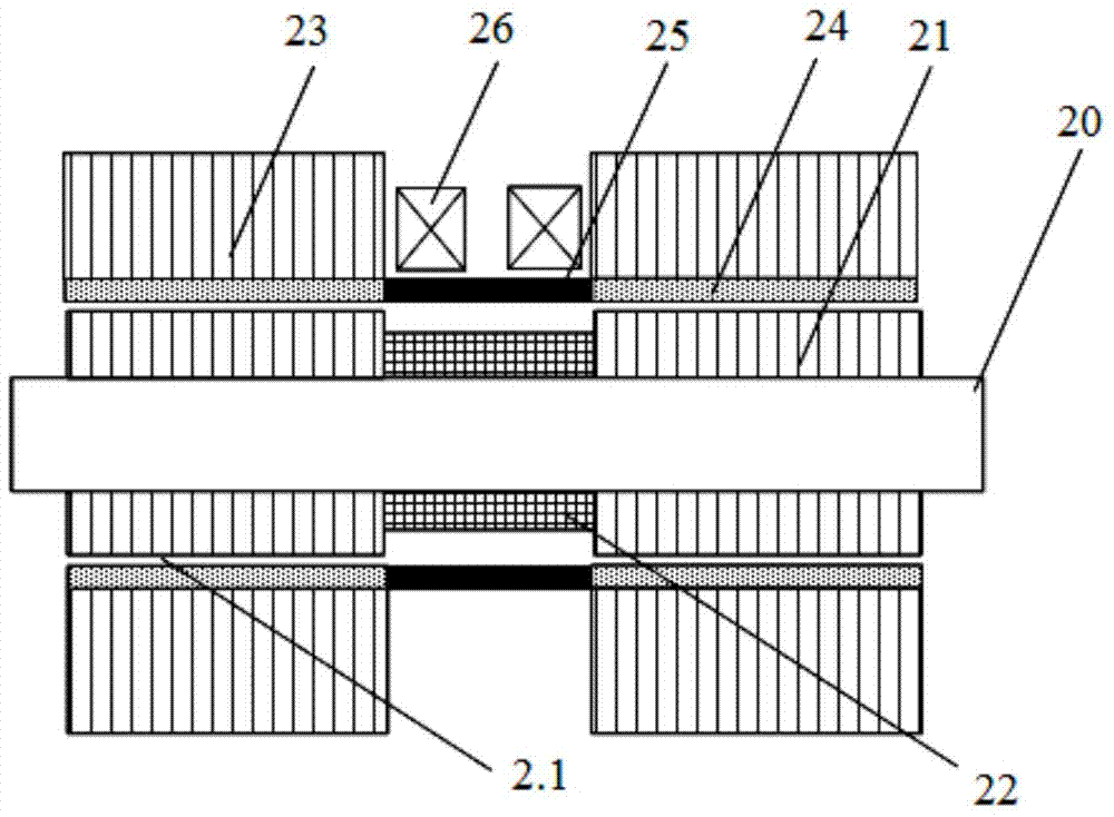
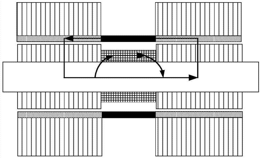
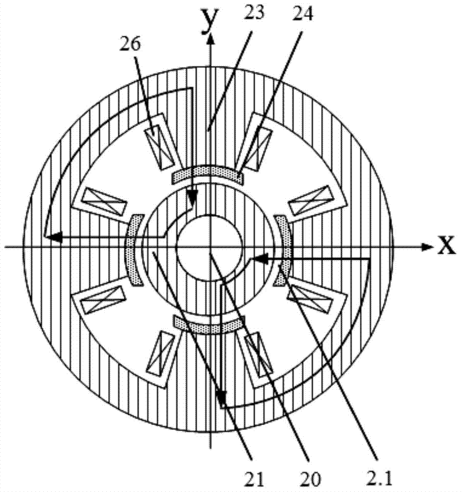
[0026] Such as figure 1 A permanent magnetic bias hybrid radial magnetic bearing is shown, including a rotor assembly and a stator assembly. The stator assembly includes two stator cores 23, each stator core 23 is provided with a magnetic block 24 at the pole shoe position, and a permanent magnet 25 is embedded between the magnetic block 24, and the material of the magnetic block 24 in this embodiment is high-permeability ...


PUM


Abstract

The invention discloses a permanent magnet polarization hybrid radial magnetic bearing. The permanent magnet polarization hybrid radial magnetic bearing comprises a rotor assembly and a stator assembly, wherein the stator assembly comprises two stator cores; a magnetic block is arranged on a magnetic pole shoe of each stator core, permanent magnets are embedded between the magnetic blocks, and a winding coil winding each magnetic pole is arranged in a radial slot of each stator core; the rotor assembly comprises a rotating shaft, rotor cores which are corresponding to the stator cores, and a magnetic ring which is arranged between the axial positions of the rotor cores; operation air gaps are formed between the magnetic blocks and the rotor cores; the size of the permanent magnets corresponding to the magnetic poles of the stator cores are same, and the same polarization force is provided for each radial direction through the operation air gaps; an electromagnetic field generated by each winding coil and a permanent magnet polarization magnetic field generated by each permanent magnet are mutually offset or overlapped, and the bearing capacity is provided for each radial direction. The permanent magnet polarization hybrid radial magnetic bearing provided by the invention has the advantages of being simple in structure and low in loss, being operated at high speed, and being particularly suitable for high-speed system which has high bearing capability and large capacity.

Description

technical field [0001] The invention relates to a non-contact high-performance magnetic suspension bearing, and more specifically, to a permanent magnet bias hybrid radial magnetic bearing with large bearing capacity and low loss. Background technique [0002] There are two types of active magnetic bearings: pure electric excitation magnetic bearings and permanent magnetic bias hybrid magnetic bearings. The former uses electric excitation magnetic fields as bias magnetic fields and has large standby losses; Regulating control, reducing control current, and reducing standby loss are the main research directions of magnetic suspension bearings at present. However, the current hybrid bias magnetic bearing structure has shortcomings to a certain extent: some structural electromagnetic magnetic circuits pass through the permanent magnet, which not only requires a large excitation current and consumes a large amount of power, but also repeatedly charges and demagnetizes the perman...

Claims


Application Information

Patent Timeline
Patent Type & Authority Applications(China)
IPC IPC(8): F16C32/04F16C33/00
Inventor 吴磊涛王东张贤彪苏振中王抗易新强魏锟
Owner NAVAL UNIV OF ENG PLA
Why Eureka
Try Eureka