

Supercavitating navigation body model with internal steering gear
A supercavitating vehicle and steering gear technology is applied in the fields of supercavitation underwater vehicle models and supercavitation vehicle models, which can solve the problems of inability to accurately capture hydrodynamic characteristics and high requirements for laboratory conditions. Achieve the effect of light weight, small size, multiple space and degrees of freedom
- Summary
- Abstract
- Description
- Claims
- Application Information
AI Technical Summary
Problems solved by technology
Method used
Image

Examples
Embodiment Construction
[0025] The specific implementation manner of the present invention will be described below in conjunction with the accompanying drawings.
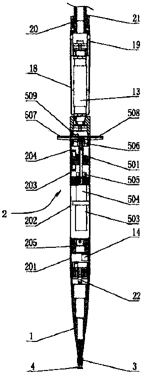
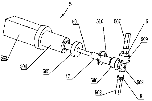
[0026] See figure 1 , figure 2 , Figure 7 , the present invention comprises a head cone section 1 and a cabin body 2, the head cone section 1 is fixedly connected to the cabin body 2, the rear end of the cabin body 2 is equipped with an empennage, and the front end of the head cone section 1 is sleeved with a ventilating bowl 3 for ventilating The front end of the bowl 3 is equipped with a cavitator 4. The cabin body 2 includes a pressure measurement cabin section 201, a motor cabin section 202, a feedback cabin section 203 and an empennage cabin section 204 arranged in sequence along the axial direction. The pin 15 is fixedly connected and sealed with an O-ring 16. A steering gear 5 is housed in the cabin body 2. The steering gear 5 includes a transmission shaft 501 and a hollow shaft 502. The transmission shaft 501 is driven by a ser...
PUM
 Abstract
Description
Claims
Application Information