Distance measurement method for power distribution network ground fault based on zero-mode travelling wave difference

A technology of ground fault and ranging method, which is applied in the fault location and uses the pulse reflection method to detect faults, etc., can solve the problems of false fault points, ranging errors, and many branches of the distribution network, so as to improve the accuracy and reduce the cost. The effect of small random disturbances

Inactive Publication Date: 2014-07-16
SICHUAN UNIV
View PDF7 Cites 12 Cited by
  • Summary
  • Abstract
  • Description
  • Claims
  • Application Information

AI Technical Summary

Problems solved by technology

[0004] For a power distribution network with a complex structure, the signal received by the detection end is the superposition of multiple refraction and reflection waves at the fault point, branch point, and branch end. It is difficult to find the reflected wave at the fault point only by using the waveform obtained after fault phase injection. The following two methods are used to extract the reflected wave of the fault point: one is to inject a high-voltage pulse signal into each phase before the system fails to obtain the non-faulted traveling wave waveform of each phase and store it, and inject the same wave into the faulty phase after the line fails The waveform of the fault condition is obtained by the high-voltage pulse signal, and the two sets of waveform data obtained by the fault phase and the non-fault condition are subtracted to extract the fault information

Method used


Image

  • Distance measurement method for power distribution network ground fault based on zero-mode travelling wave difference
  • Distance measurement method for power distribution network ground fault based on zero-mode travelling wave difference
  • Distance measurement method for power distribution network ground fault based on zero-mode travelling wave difference

Examples


Embodiment 1

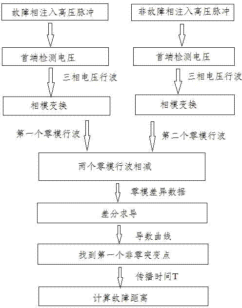
[0045] A distance measurement method for a distribution network ground fault based on zero-mode traveling wave difference, comprising the following steps:

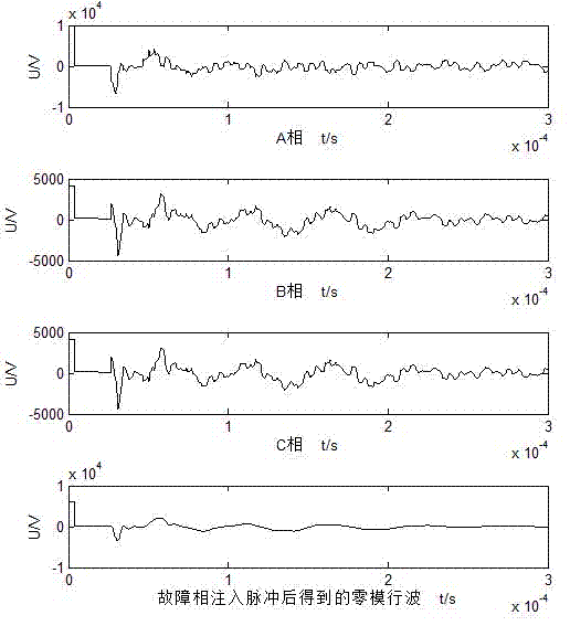
[0046] (A) Inject high-voltage pulses into the faulty phase at the first end of the distribution network, and detect the voltage traveling waves returned by the three phases. The voltage traveling waves returned by the three phases are transformed by phase mode to obtain the first zero-mode voltage traveling wave data; the injected high voltage The pulse is a high-voltage pulse with a pulse width of Xμs and an amplitude of YkV, such as image 3 , detect the voltage traveling wave returned by the three phases and obtain the corresponding zero-mode voltage traveling wave;

[0047] (B) Inject a high-voltage pulse consistent with step (A) into a non-faulty phase at the head end of the distribution network, and detect the voltage traveling waves returned by the three phases. The traveling voltage waves returned by the three pha...

Embodiment 2

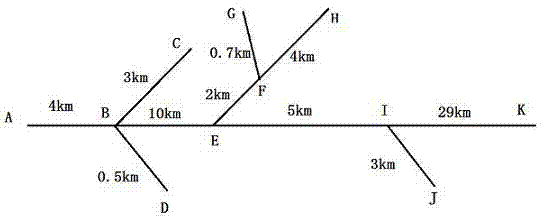
[0065] Such as figure 1 As shown, this embodiment is an experiment of single-phase ground fault distance measurement in a distribution network, using the Frequency Dependent Models in PSCAD (Power Systems Computer Aided Design); figure 2 It is the structure diagram of the experimental circuit, A is the head end of the line (that is, the detection point), and the end of each branch is connected with a 10kV / 0.4kV distribution transformer (Dyn or Yyn connection) and a three-phase unbalanced load, and the sampling frequency is 10MHz. Setup failure occurs at figure 2 For the EI section line from point E to point I, the grounding resistance is 100Ω, and the distance from the head end is 17km. The above is the element setting.

[0066] First, a high-voltage pulse with a pulse width of 4μs and an amplitude of 10kV is injected into the faulty phase at the head end of the line (at point A), and the voltage traveling wave returned by the three phases is detected, and used Get the f...

Embodiment 3

[0068] A distance measuring method for a distribution network ground fault based on zero-mode traveling wave difference, comprising the following steps: wherein phase A is a fault phase, and phase B and phase C are non-fault phases;

[0069] (A) Inject high-voltage pulses into phase A (faulty phase) at the head end of the distribution network, and detect the traveling voltage waves returned by the three phases. The traveling voltage waves returned by the three phases are transformed by phase mode to obtain the first zero-mode voltage traveling wave data ; The injected high-voltage pulse is a high-voltage pulse with a pulse width of Xμs and an amplitude of YkV, such as image 3 , detect the voltage traveling wave returned by the three phases and obtain the corresponding zero-mode voltage traveling wave;

[0070] (B) Inject a high-voltage pulse consistent with step (A) into phase B (non-fault phase) or phase C (non-fault phase) at the head end of the distribution network, and de...


PUM


Abstract

A distance measurement method for a power distribution network ground fault based on the zero-mode travelling wave difference comprises the following steps: (A) injecting high voltage pulses into fault phases of the head end of a power distribution network, detecting voltage travelling waves returned by the three phases, and obtaining first zero-mode voltage travelling wave data with the voltage travelling waves returned by the three phases through phase-mode transformation; (B) injecting high voltage pulses consistent with the high voltage pulses in the step (A) into a certain healthy phase of the head end of the power distribution network, detecting travelling waves returned by the three phases, and obtaining second zero-mode voltage travelling wave data with the travelling waves returned by the three phases through phase-mode transformation; (C) conducting subtraction on the first zero-mode voltage travelling wave data obtained in the step (A) and the second zero-mode voltage travelling wave data obtained in the step (B) to obtain difference data; (D) conducting different derivation on the difference data obtained in the step (C) to obtain a first non-zero mutational site moment, and then obtaining propagation time of the travelling waves; (E) substituting the propagation time obtained in the step (D) into a distance measurement formula to obtain a fault distance.

Description

technical field [0001] The invention relates to a traveling wave ranging method, in particular to a method for injecting traveling wave ranging based on a single-phase grounding fault of a distribution network based on zero-mode traveling wave difference. Background technique [0002] my country's 6~35kV distribution network generally operates in the neutral point non-direct grounding mode. After a single-phase ground fault accounts for 50%~80% of the total faults, the traditional processing method uses manual line inspection to find the fault point, which is time-consuming and laborious. Research on accurate and effective single-phase ground fault location method is of great significance for improving the power supply reliability of distribution network and reducing power failure loss. [0003] At present, there are two main development directions of distribution network fault location methods: the method based on distribution network automation system and the traveling wav...

Claims


Application Information

Patent Timeline
IPC IPC(8): G01R31/11
Inventor 周聪聪舒勤钟俊刘朕志董丽梅
Owner SICHUAN UNIV
Why Eureka
Try Eureka