
Laser pulse distance measurement method based on light path differences

A technology of laser pulse and ranging method, which is applied in the direction of measuring device, electromagnetic wave reradiation, radio wave measuring system, etc., can solve the problems affecting ranging accuracy and signal-to-noise ratio reduction, which is beneficial to the improvement of precision and the benefit of The effect of the hardware implementation

Inactive Publication Date: 2014-12-31
BEIJING INSTITUTE OF TECHNOLOGYGY
View PDF5 Cites 0 Cited by
  • Summary
  • Abstract
  • Description
  • Claims
  • Application Information

AI Technical Summary

Problems solved by technology

[0003] The purpose of the present invention is to solve the problem that the distance measurement accuracy is affected by the decrease of signal-to-noise ratio, and to provide a laser pulse distance measurement method based on optical path difference

Method used


Image

  • Laser pulse distance measurement method based on light path differences
  • Laser pulse distance measurement method based on light path differences
  • Laser pulse distance measurement method based on light path differences

Examples


Embodiment 1

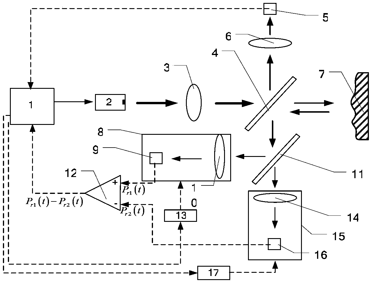
[0028] A laser pulse ranging method based on optical path difference, the structure is as follows figure 1 As shown, it includes a processing circuit module 1, a laser light source 2, a collimator beam expander 3, a beam splitter 4, a photodetector 5, a condenser lens 6, a first coarse and fine motion platform 8, a first APD9, a first receiving lens 10, Half mirror 11, subtractor 12, first coarse and fine motion platform controller 13, second receiving lens 14, second coarse and fine motion platform 15, second APD16, second coarse and fine motion platform controller 17;

[0029] Wherein, the distance between condenser lens 6 and beam splitter 4 is denoted as 1 0 , l 1 Be the distance between the beam splitter 4 and the half mirror 11, the distance between the beam splitter 4 and the first receiving lens 10, the second receiving lens 14 is denoted as 1 2 , l 3 , in order to realize the optical path difference, the following relationship is satisfied: l 1 +l 2 =l 0 -d, l ...


PUM


Abstract

The invention belongs to the field of laser distance measurement and particularly relates to a laser distance measurement method based on light path differences. According to the laser pulse distance measurement method based on the light path differences, a system comprises a processing circuit module, a laser light source, a collimation beam expander, a spectroscope, a photoelectric detector, a collecting lens, a first coarse micro-positioning platform, a first APD, a first receiving lens, a half-reflective half-transparent lens, a subtracter, a first coarse micro-positioning platform controller, a second receiving lens, a second coarse micro-positioning platform, a second APD and a second coarse micro-positioning platform controller. According to the laser pulse distance measurement method based on the light path differences, a dual-APD detector is adopted to receive echoes, meanwhile, the subtracter is used for obtaining difference echo signals, influence of background noise on distance measurement is effectively eliminated, and the system can conduct effect measurement in medium and far distances.

Description

technical field [0001] The invention belongs to the field of laser ranging, in particular to a laser ranging method based on optical path difference. Background technique [0002] Laser pulse ranging is to use a laser to emit a narrow pulse to the target, measure the time of flight (TOF: time of flight) of the laser pulse between the target and the sensor, and then calculate the distance between the two. Because the TOF-based measurement method has the characteristics of long measurement distance, high precision, simple structure, and stable performance, it is widely used for distance measurement of targets such as tanks, aircraft, ships, and artillery, as well as terrain measurement, battlefield measurement, clouds, aircraft, Missile and artificial satellite altitude measurement, etc. At present, laser ranging usually uses a single high-sensitivity photoelectric receiver (for example: avalanche photodiode (APD)) for medium and long-distance targets, combined with the echo ...

Claims


Application Information

Patent Timeline
Patent Type & Authority Patents(China)
IPC IPC(8): G01S17/32
Inventor 郝群曹杰宋勇李腾飞杨云翼徐英莹
Owner BEIJING INSTITUTE OF TECHNOLOGYGY
Learn More